The Su-27 (NATO codename Flanker B) is a highly-agile, supersonic, twin-engine air-superiority fighter. A mainstay of modern Russian combat aviation, the Su-27’s primary role is as a long-range interceptor, but it is also a superb dogfighter. The Flanker B can carry up to twelve air-to-air missiles - usually a mix of short range R-73s (AA-11 Archer) all-aspect IR and medium-to-long range R-27s (AA-10 Alamo). It also has a fearsome 30 mm GSh-30-1 cannon and can deliver unguided bombs, CBUs and rockets in the ground attack role.
Equipped with a powerful (‘Slot Back’, Russian ‘Mech’ or ‘Sword’) pulse doppler radar for optimum lookdown-shootdown capability, the Su-27 also has cutting-edge Infrared Search and Track (IRST) for the passive detection and engagement of aerial targets.
Powered by 2 × Saturn AL-31F turbofans each producing 16,910 lbf of dry thrust and 27,560 lbf with afterburner, the Flanker B has a maximum speed of 2,500 km/h (1,550 mph or Mach 2.35) at altitude and 1,400 km/h (870 mph or Mach 1.13) at sea level and a searing 59,000 ft/min rate of climb. The aircraft has a service ceiling of 62,500 ft and an exceptional range of 3,530 km (2,193 mi; 1,906 nmi) at altitude and 1,340 km (800 mi; 720 nmi) at sea level.
Fast, agile and superbly equipped, the Su-27's ability to maneuver at very slow speed and with a high angle-of-attack make it a dangerous opponent in air combat. Take on the DCS: F-15C Eagle - and see who comes out on top. The J-11A aircraft featured in the game is a Chinese variant of the Russian Su-27 with minor radar modifications and the ability to use R-77 active air-to-air missiles.
The Su-27, NATO codename Flanker, is one of the pillars of modern-day Russian combat aviation. Built to counter the American F-15 Eagle, the Flanker is a twin-engine, supersonic, highly manoeuvrable air superiority fighter. The Flanker is equally capable of engaging targets well beyond visual range as it is in a dogfight given its amazing slow speed and high angle attack manoeuvrability. Using its radar and stealthy infrared search and track system, the Flanker can employ a wide array of radar and infrared guided missiles. The Flanker also includes a helmet-mounted sight that allows you to simply look at a target to lock it up! In addition to its powerful air-to-air capabilities, the Flanker can also be armed with bombs and unguided rockets to fulfil a secondary ground attack role. The J-11A aircraft featured in the game is a Chinese variant of the Russian Su-27 with minor radar modifications and the ability to use R-77 active air-to-air missiles.
Su-27 for DCS World focuses on ease of use without complicated cockpit interaction, significantly reducing the learning curve. As such, Su-27 for DCS World features keyboard and joystick cockpit commands with a focus on the most mission critical of cockpit systems.
The main feature for the success of the Su-27 design is its aerodynamic configuration, known as "integrated aerodynamic concept" by its designers. This configuration is one with extremely blended wing and fuselage. The low-aspect ratio trapezoidal midwing is fitted with large leading-edge root extensions (LERX) and blending into the fuselage creating a single lifting body.
The aircraft has a near-zero static stability and thus require a fly-by-wire system. The SDU-10 pitch-only fly-by-wire system controls the pitch of the aircraft to ensure stability and controllability for the pilot, increase aerodynamic performance, limit overload and angle of attack when needed and decrease the airframe aerodynamic load.
Two AL-31F afterburning turbofans are placed in seperate, widely spaced engine nacelles that are mounted under the lifting body. The air intakes are fitted with variable ramps.
The Su-27 has twin vertical fins fitted on the outer sides of the fuselage and twin central fins underneath. The airbrake is placed in the center of the mid-section of the aircraft behind the cockpit. The tricycle landing gear of Su-27 and Su-27UB has a single wheel on each strut. The nose wheel is fitted with a mudguard to protect against foreign object damage (FOD).
The basic Su-27 is fitted with the SUV-27 fire control system, which incorporates the RLPK-27 radar sighting system, OEPS-27 electro-optical sighting system, SEI-31 integrated indication system, IFF interrogator and built-in test system. The fire control system in integrated with the PNK-10 flight navigation system, radio command link, IFF system, data transmission equipment and EW self-defence system.
The RLPK-27 system and is controlled by the Ts-100 digital computer and includes the N001 pulse-Doppler lookdown-capable radar with a range of 80-100 km in the front hemisphere and 30-40 km in the rear hemispehere for a fighter-sized target. It can simultaneously track up to ten aerial targets in track-while-scan mode and provide interception of the top priority target.

The OEPS-27 electro-optical sighting system consist of the OLS-27 infrared/laser search-and-track system (IRST) and the Shchel-3UM helmet-mounted target designator and is controlled by the Ts-100 digital computer. The OLS-27 sensor is placed forward of the cockpit canopy in the centre. The system acquires and tracks aerial targets by their thermal signatures. The helmet-mounted sight and the laser range finder of the IRST can also be used to visually acquire and determine coordinates of air and surface targets.
The SEI-31 integrated indication system provides flight, navigation and sighting data on the ILS-31 head-up display (HUD) and head down display. The EW self-defence systems provides warning to the crew when illuminated by enemy radar and employs both passive and active countermeasures. The aircraft is equipped with the SPO-15 Beryoza RWR and APP-50 chaff and flare dispenser that is placed in the tail section between the engine nozels. In addition, the aircraft can carry the Sorbtsiya active ECM pods on its wingtips.
The basic Su-27 cockpit layout consist of analogue instruments, HUD and head down display to display data from radar and electro-optical sight (IRST). On both sides of the HUD control panel, there are sensors for the helmet-mounted target designator system. On the right side below the Head Down Display the RWR indicator is placed.
|
Takeoff weight: - normal (including 2xR-27R + 2xR-73, 5270 kg fuel), kg - maximum, kg |
23,430 30,450 |
| Maximum landing weight, kg | 21,000 |
| Max landing weight, kg | 23,000 |
| Maximum internal fuel, kg | 9,400 |
| Maximum ordnance, kg | 4,430 |
| Service ceiling (without external ordnance and stores), km | 18.5 |
| Maximum flight speed at sea level (without external ordnance and stores), km/h | 1,400 |
| Max Mach (without external ordnance and stores) | 2.35 |
| G-limit (operational) | 9 |
|
Maximum flight range (with missiles 2xR-27R, 2xR-73 launched at half distance): - at sea level, km - at height, km |
1,340 3,530 |
| Maximum airborne time, hours | 4.5 |
| Take-off run at normal takeoff weight, m | 450 |
| Landing run at normal landing weight (with braking parachute), m | 620 |
|
Aircraft dimensions: - length, m - wingspan, m - height, m |
21.9 14.7 5.9 |
| Crew | 1 |
| Number and type of engines | 2xAL-31F |
|
Thrust: - in afterburner, kgf - at full power, kgf |
12,500 7,670 |
Guns: 1 x 30 mm GSh-301 cannon, 150 rounds
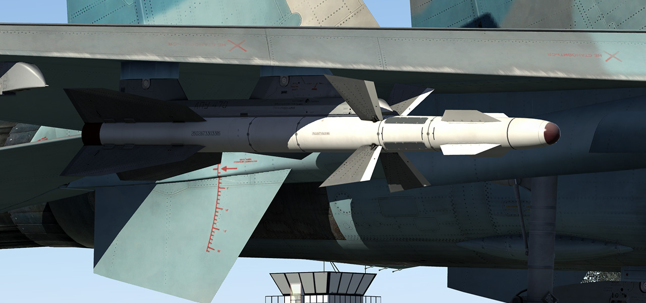
Up to 6 x R-27R SARH air-to-air missiles
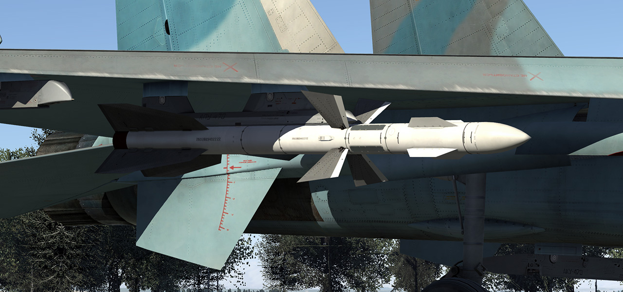
Up to 6 x R-27ER SARH air-to-air missiles extended range

2 x R-27T IR air-to-air missiles
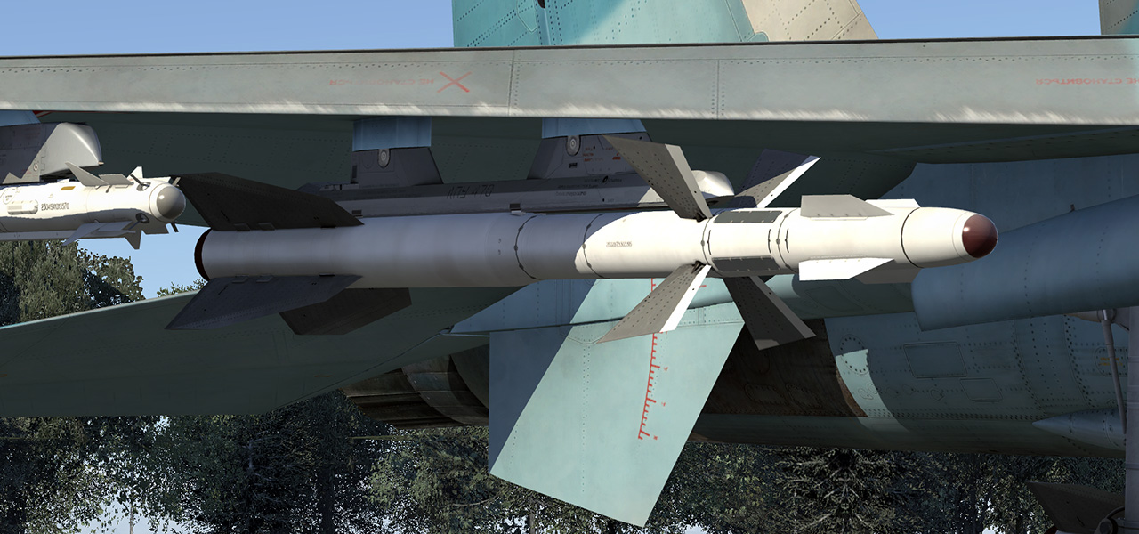
2 x R-27ET IR air-to-air missiles extended range
Up to 6 x R-73 IR air-to-air missiles
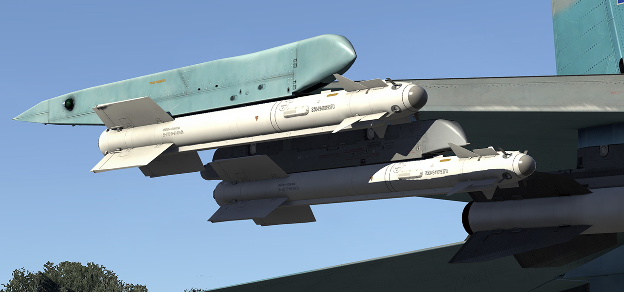
Su-27 can carry a solid list of non guided bombs and rockets.
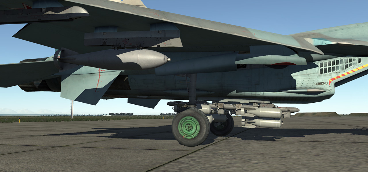
High explosive general purpose bombs FAB-100, FAB-250, FAB-500.
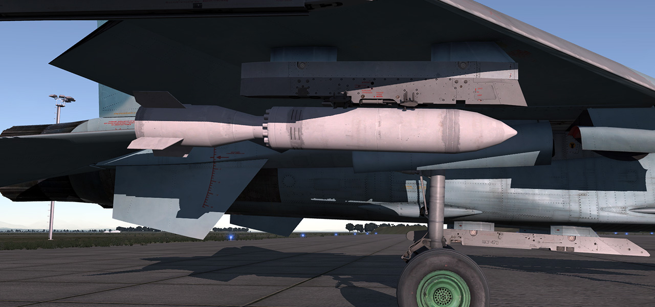
Concrete piercing bombs BetAB-500.
Cluster munitions RBK-250, RBK-500, KMGU.

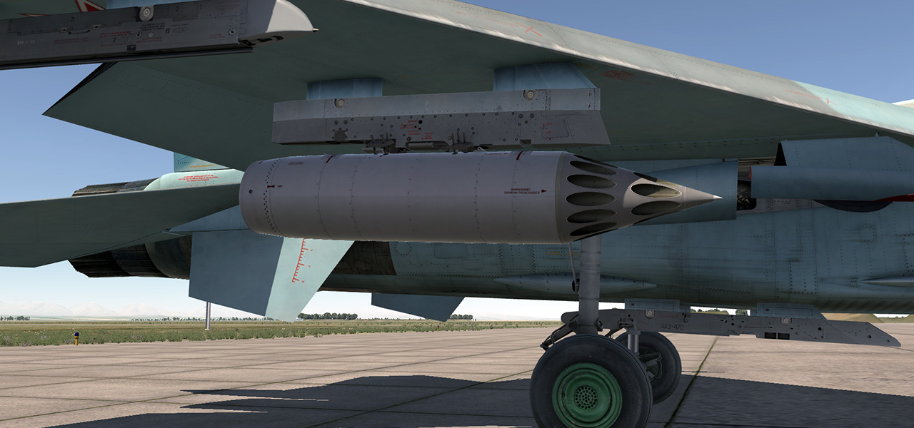
Rockets S-8, S-13, S-25.
Illumination bomb SAB-100.
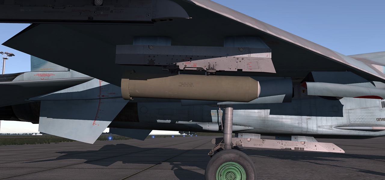
The Su-27 is controlled by a combination of mechanical and fly-by-wire sub-systems. The longitudinal control is maintained by the synchronous deflection of stabilizers and lateral control is maintained by the differential deflection of flaperons, stabilizers, and rudders. Directional control is maintained by the deflection of rudders.
The mechanical control system is intended for differential deflection of flaperons as part of the lateral control system; synchronous deflection of flaperons during takeoff and landing; rudder deflection during pedal movement; and artificial flight control loading and trimming.
The fly-by-wire system is intended for manual control of the aircraft via longitudinal and lateral channels to provide desired stability and control qualities; to limit angle-of-attack and g load; to control wing leading edges; and for synchronous control of flaperons during maneuvering.
In order to improve maneuvering performance, the Su-27 has a low degree of pitch stability, which resulted in the necessity of using the fly-by-wire system for augmenting control stability of the aircraft.

Longitudinal channel stabilizer control schematic block diagram
The longitudinal channel of the fly-by-wire system has three operational modes:
The TAKEOFF-LANDING and FLIGHT modes of the fly-by-wire system are switched automatically in accordance with landing gear position.
The DIRECT CONTROL mode is switched on if the fly-by-wire system fails. Piloting in this mode requires special care; the flight is characterized by:
When in this mode, compensate for the aircraft’s tendency to change pitch by using short, preemptive stick inputs. Refrain from abrupt, large stick inputs. Angle of attack in this mode should not exceed 10 degrees (the flight envelope limiter does not restrict the angle in this mode); perform turns with a bank no more than 45 degrees.
It is in this mode that the "Pougachev’s Cobra" aerobatic maneuver is performed.
The fly-by-wire system is a trajectory control system. In other words, if the control stick remains in the same position, the system will hold the set flight path. This is why the reduction of airspeed (for example) and resulting decreased lift and increasing angle of attack, will lead to the aircraft attempting to hold the initial flight path and prevent the aircraft from descending. This will result in the airspeed stability degradation up to neutral stability.
The longitudinal control system includes an airspeed trimming law that generates a signal proportional to the ram air. When the indicated airspeed is increased, the FCS causes the stabilizers deflection (up to 5 degrees) nose down. When decelerating, it causes the nose to come up. This imitates the airspeed stability of the aircraft, which is neutral in the presence of a g loading feedback signal. The airspeed stability imitation allows the pilot to use the control stick like he or she would with a stable aircraft.

Stabilizer trimming (ST) – ram-air flow (CAS) diagram
This is a logic law of the FBW and is based on tick longitudinal deflection vs ram air pressure. This control law makes the pilot "feeling" of flying at an airspeed-stable aircraft. The law is also intended to increase the flight safety when decelerating. As the aircraft is neutrally stable by airspeed, it should increase the angle of attack in decelerated flight. The aforementioned control law prevents from this by deflecting stabilizers to decrease the AoA.
When accelerating, to keep the aircraft level, it should be trimmed "nose down" as the airspeed increases.
Roll control is performed by flaperons working as ailerons (flaperons are also deflected down as flaps when in the takeoff-landing mode) and by differential stabilization. With increased angle of attack, the rudders are used to control roll (see Directional channel).

Lateral channel stabilizer control schematic block diagram
The flaperons and rudders belong to the mechanical part of the control system. The lateral channel of the fly-by-wire system, which includes differential control mechanism and roll damper, controls the differential stabilizer deflection.
The differential control mechanism is actuated by side stick inputs and provides differential stabilizer deflection. The degree of this deflection depends on the indicated airspeed and angle of attack.

AoA and CAS correction of the differential stabilizer
Reduction of differential stabilizer deflection as V increases excludes large loads on the fuselage tail section at high indicated airspeeds and their reduction with the angle of attack increase excludes manifestation of roll yaw reversal.
The roll damper provides differential stabilizer deflection by roll rate, and it is intended to counteract short-period, roll oscillations.
As indicated airspeed increases at low-to-medium altitude, the maximum roll rate ωх max is increased, reaching the highest value within an indicated airspeed of 600...800 km/h. Here, the maximum ease of the lateral aircraft control is observed.
With a further increase of the indicated airspeed, the lateral handling gradually deteriorates, which becomes noticeable at airspeeds greater than 1200 km/h.

Roll rate – CAS diagram
Such dependence of the lateral handling based on indicated airspeed is accounted for by the following factors:
Directional yaw control is performed by symmetrical deflection of the rudders. Transmission of inputs from pedals to the rudders is conducted by means of a mechanical linkage. Additionally, yaw sub-channel servo units of the fly-by-wire system are mechanically connected to the rudders with half-travel authority.

Directional channel rudder control schematic block diagram
The yaw sub-channel of the fly-by-wire system includes the following automatic devices:
Roll-Yaw crossfeed system operates in accordance with side stick inputs. It deflects the rudders to the same side as the control stick. This eliminates adverse sideslip caused by the difference in drag by half-wings. It also improves a lateral controllability, especially at high angles of attack.

Rudder – AoA diagram
Due to this, lateral control is preserved up to an angle of attack of 28 degrees and there is no roll reversal due to control stick movement.
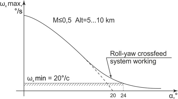
Roll rate – AoA diagram
Yaw stability system operates in accordance with lateral acceleration inputs and it provides required characteristics for aircraft yaw stability due to the aircraft having relaxed statistic yaw stability. This is due to the peculiar properties of the Su-27’s aerodynamic configuration aft of the center of gravity, elongated lateral wing area of the fuselage, and forward fin displacement. The operating principle of the Su-27’s yaw stability system is similar to that of the pitch stability augmentation system.
Yaw damper provides the required characteristics needed for lateral dynamic stability.
In order to decrease loads on the fins and the aft fuselage as a whole at the speeds of over 600 km/h, and when the landing gear is up, a spring mechanism is connected to the directional control system providing for the locking stop in the mid-travel of the pedals to each side. It is forbidden to override the locking stop of the pedals at the airspeeds over 600 km/h. This is why pedal travel at these speeds is reduced by half in this simulation.
The powerplant of the Su-27 includes two АЛ-31Ф (AL-31F) engines, each of which has its own turbine starter ГТДЭ-117 (GTDE-117). Because both engine have a separate starter, both individual and simultaneous starting of both engines is possible.
In order to start the engines on the ground, one should:
After this, the engine starter doors will open, the door limit switch actuates and puts the starter circuit into operation. Based on the starter circuit command, fuel is provided to the turbine starter and the annunciator "ЗАПУСК" (START) is lit in the cockpit.
The starter circuit turns on the electrical starter motor, ignites the turbine starter, and supplies oxygen to the turbine starter. After ten seconds, the turbine starter will turn off these accessories and simultaneously turns on ignition of the main chamber. The turbine starter spins up the engine rotor and the fuel control unit controls fuel flow to the main chamber. After ignition in the main chamber, the turbine comes into operation and accelerates the engine rotor together with the turbine starter. At 35% of the engine RPM, the ignition exciter in the main chamber switches off. At 53% of the engine RPM, or after 50 seconds, the turbine starter and starter circuit are switched off, which is indicated by the annunciator "ЗАПУСК" (START) turning off. The engine then reaches IDLE mode automatically.
The nozzle control system is intended to change the diameter of the exhaust nozzle in accordance with the desired law.
Before engine start, during the ignition and when in IDLE mode, the nozzles are completely open to provide the most favorable conditions for engine start: the greatest torque of the turbine, minimum overheating, and the minimum thrust during IDLE mode. When the throttle is moved forward to 77-81% of the engine RPM, the nozzles close partially in order to produce improved thrust characteristics. When the afterburner is switched on, the nozzles opens in order to maintain the turbine exhaust temperature. As the thrust augmentation ratio increases, the nozzles open.
When the landing gear is extended, the nozzles partially closed in order to preserve the power margin and to avoid nozzle contact with the runway during the touchdown. Due to this, the thrust is increased when on the glide path. In order to decelerate, the speedbrake should be used.


