DCS: Black Shark 2 is a simulation of the Russian Ka-50 attack helicopter and the next entry in the Digital Combat Simulator combat series. DCS: Black Shark 2 is a greatly improved version of the original DCS: Black Shark that brings many new features.
The Ka-50 "Black Shark" is a unique and deadly single-seat, Russian attack helicopter that has seen combat in the Northern Caucasus. It combines a high performance dual rotor system with a deadly weapons payload of guided missiles, rockets, bombs, and a 30mm cannon. The Ka-50 is also unique in that it has an ejection seat.
DCS: Ka-50 Black Shark is a PC game of the Russian Ka-50 attack helicopter and is the first title in a new Eagle Dynamics and The Fighter Collection simulation series: Digital Combat Simulator (DCS). Following Eagle Dynamics tradition of excellence, DCS: Ka-50 Black Shark will bring an even more realistic simulation experience than its predecessor LockOn: Flaming Cliffs.
DCS: Ka-50 Black Shark will offer an unprecedented level of realism in regards to flight dynamics, instruments modeling, avionics systems, and weapon systems. The artificial Intelligence of ground vehicles and helicopters has been improved dramatically as well as weapon modeling. A new Mission Editor includes a powerful electronic mapping system that allows user to easily create missions and campaigns. A new campaign system allows the front line of the battlefield to move back and fourth according to your mission success or failure. Due to the increased flexibility of the DCS system, additional fixed-wing aircraft and helicopter add-ons will follow shortly.
The Ka-50 flight and systems model has been implemented using the following methodologies.
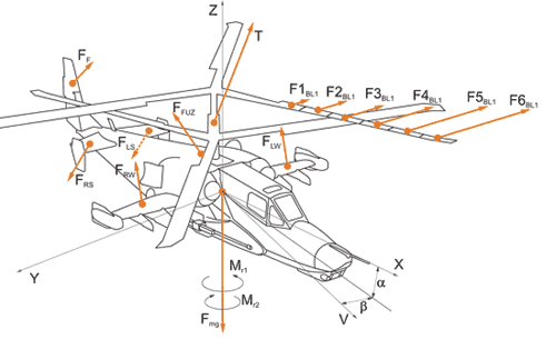
Rigid body dynamics equations have been used to calculate the helicopter's flight trajectory. In essence, this means that all external forces and force momentums are used to calculate a body's position and rotation in 3-D space.
The Ka-50 airframe aerodynamic properties are derived from its sub-element parameters: fuselage, wings, tail, and landing gear. Each of these has its own position and orientation within the airframe local-coordinate system and each has their own aerodynamic characteristics. Each sub-element is calculated by independent lift-drag coefficients diagrams, damage degree influencing the lift properties, and center of gravity (CG) position and inertial characteristics. Aerodynamic forces acting on each sub-element of the airframe are calculated separately in their own coordinate system taking into account local airspeed of the sub-element.
Contacts with the ground and external objects are modeled based on rigid contact points system.
Landing gear is modeled as separate gear arms, each consisting of a wheel and an asymmetric shock absorber. The nose wheel is self-orienting, based on acting external forces. Such a model allows for modeling of realistic behavior including the development of shimmy effects at high speeds. Retracting and lowering the landing gear can lead to CG repositioning. When modeling landing gear operations their kinematic properties, external and hydraulic forces are all taken into account. The result is very realistic behavior in all conditions.
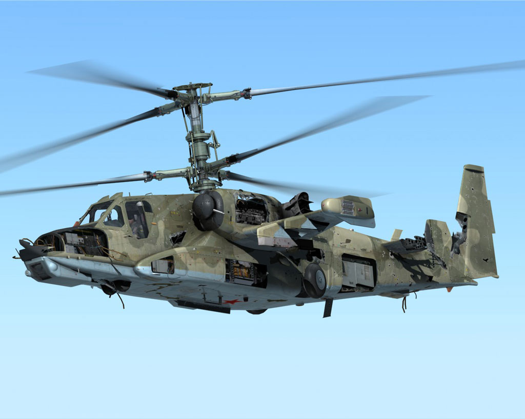
The damage model is based on aerodynamic and rigid contact forces where applicable. Damages to airframe components, landing gear, wheels, sensors and devices are all taken into account. Any damage will affect the helicopter's physical and functional properties and reposition the CG.
The Ka-50 Black Shark's rotor model is revolutionary among helicopter simulators. It is based on a joint model of each blade with its own complex motion relative to rotor axis and flapping (horizontal) and hunting (vertical) hinges. Each blade is separated into multiple segments, each having its own air velocity vector based on its orientation, twist, and induced velocity at current rotor section. Induced velocity is calculated by solving the equations based on simultaneously application of motion quantity theorem and blade element method. All this produces natural helicopter dynamics such as conical rotor inclination in forward flight (oscillations in hover with fixed stick, cyclic stick input increasing accordingly to the airspeed), power excess after transition from hover to forward flight, ground effect (over inclined surface or close to ground objects), «vortex ring» phenomena, airflow stall from the blades, blades intersection (collision). In the case of individual blade damage, corresponding dynamics are naturally modeled as part of overall rotor model.
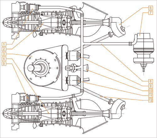
The Ka-50 powerplant consists of a gearbox with free-wheel clutches, two TV3-117VMA turbo-shaft engines with electronic engine governors, an auxiliary power unit and turbo-gear.
For the first time in flight simulation history, the engine model is based on detailed physics model of turbo-shaft engine as a system of separate components of the engine gas-dynamics system: engine inlet, compressor, combustion chamber, high-pressure turbine and power-turbine with engine exhaust.
The model corresponds to the real engine in all modes of operation in terms of output power, acceleration, compressor RPM, exhaust gas temperature (EGT) and fuel consumption, in relation to the ambient air temperature and pressure. Operation of bleed air valves is modeled for the compressor anti-stall system, engine's deicing system and the dust cyclone. By reducing the airflow through the engine, these devices increase the EGT and lower the take-off power of the engine. Engine components parameters degradation is implemented in the model within the service life or in case of exceeded operation limitations of take-off and emergency power modes or power loss with EGT over-limit.
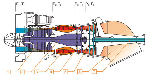
Compressor choking caused by intake icing is modeled so that it leads to power loss, EGT increase, compressor stall and engine flame-out. Flame-out is modeled using air-fuel ratio calculation in the combustion chamber.
The engine control system, as in real life, consists of turbo-compressor (gas-generator- GG) RPM governor, power-turbine RPM governor, automatic engine start-up and acceleration devices, electronic engine governor (EEG) that limits the max EGT and monitors/limits the power-turbine RPM. Except for direct engine control, the control system incorporates start-up cycle of the APU, main engines and turbo-gear, engine and engine controls test equipment like engine false start, engine vent (crank), EEG test, rotor (power-turbine) RPM governor readjustment and many more.
The hydraulic system incorporates all of the servo boosters, accumulators, tanks, and boost pumps. As in the real system, it is subdivided into Main and Common systems, each having its own lines, pumps and consumers. In the servo booster model, the displacement of the output power rod as a function of the fluid pressure (and selector valve position) is taken into account along with external factors such as hinge moments, support reactions etc. The system pressure is determined by the charge in the accumulators as a function of the pumps delivery and loads consumption and also damage leaks.
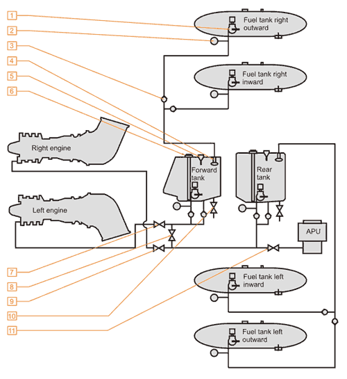
Helicopter's fuel system includes fuel tanks, fuel lines, boost pumps and valves. Fuel usage leads to change in the center of mass position within allowed operating limits. Fuel system is fully controlled from the cockpit by the pilot.


