The UH-1 ‘Iroquois’ is a light multirole utility and combat helicopter. Better known as the ‘Huey’ from its original ‘HU-1’ designation, the UH-1 is one of the world’s most iconic helicopters. A mainstay of U.S. forces in the Vietnam War, the Huey shot to fame following its starring roles in Hollywood blockbusters The Deer Hunter (1978) and Apocalypse Now (1979).
Known as a ‘slick’, the Huey’s primary mission was to insert and extract combat troops. Airborne assaults in Vietnam consisted typically of up to 10 slicks ferrying infantry, with two or three gunships providing protection and a ‘Charlie/Charlie’ Command and Control helicopter orbiting overhead. The Huey’s other missions included forward supply; search and rescue (SAR); reconnaissance and the medical evacuation (Medevac) of injured troops. The UH-1H can carry 4000 lbs of weapons & cargo including up to 14 combat troops or 6 stretchers. Armed with rockets and machine guns, it can also act as an ad hoc gunship.
Developed in the 1950s, the UH-1 entered service in March 1961. The UH-1H with the uprated 1,400 shp (1,000 kW) Lycoming T53-L-13 is the most-produced variant of the 16,000-plus that have been built since then. The Huey continues to serve worldwide in both military and civilian roles.
The DCS: UH-1H features an updated model of the helicopter armed with rockets and door-mounted M134 six-barrel rotary miniguns. The simulation offers superb flight and systems modeling. Helpful Easy Flight and other modes reduce the learning curve for new players. Player positions include pilot, co-pilot, and door gunners. A handcrafted storyline campaign is included as well as a number of single missions and a training course.
A robust and trustworthy work-horse, the UH-1 evokes enormous affection from former crews. When you fly it, you will immediately understand why.
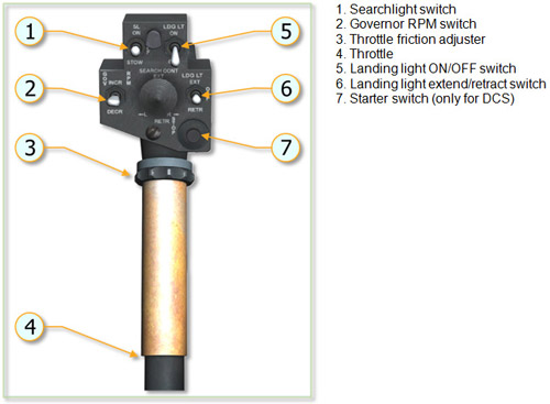
The collective pitch control lever controls vertical flight. When the lever is in full down position, the main rotor is at minimum pitch. When the lever is in the full up position, the main rotor is at maximum pitch. The amount of lever movement determines the angle of attack and lift developed by the main rotor, and results in ascent or descent of the helicopter. Desired operating friction can be induced into the control lever by hand-tightening the friction adjuster. A grip-type throttle and a switch box assembly are located on the upper end of the collective pitch control lever. The pilot switch box contains the starter switch, governor rpm switch, engine idle stop release switch, and landing light/searchlight switches. A collective lever down lock is located on the floor below the collective lever. The copilot collective lever contains only the grip-type throttle, governor rpm switch, and starter switch when installed. The collective pitch control system has built-in breakaway (friction) force to move the stick up from the neutral (center of travel) position of eight to ten pounds with hydraulic boost ON.
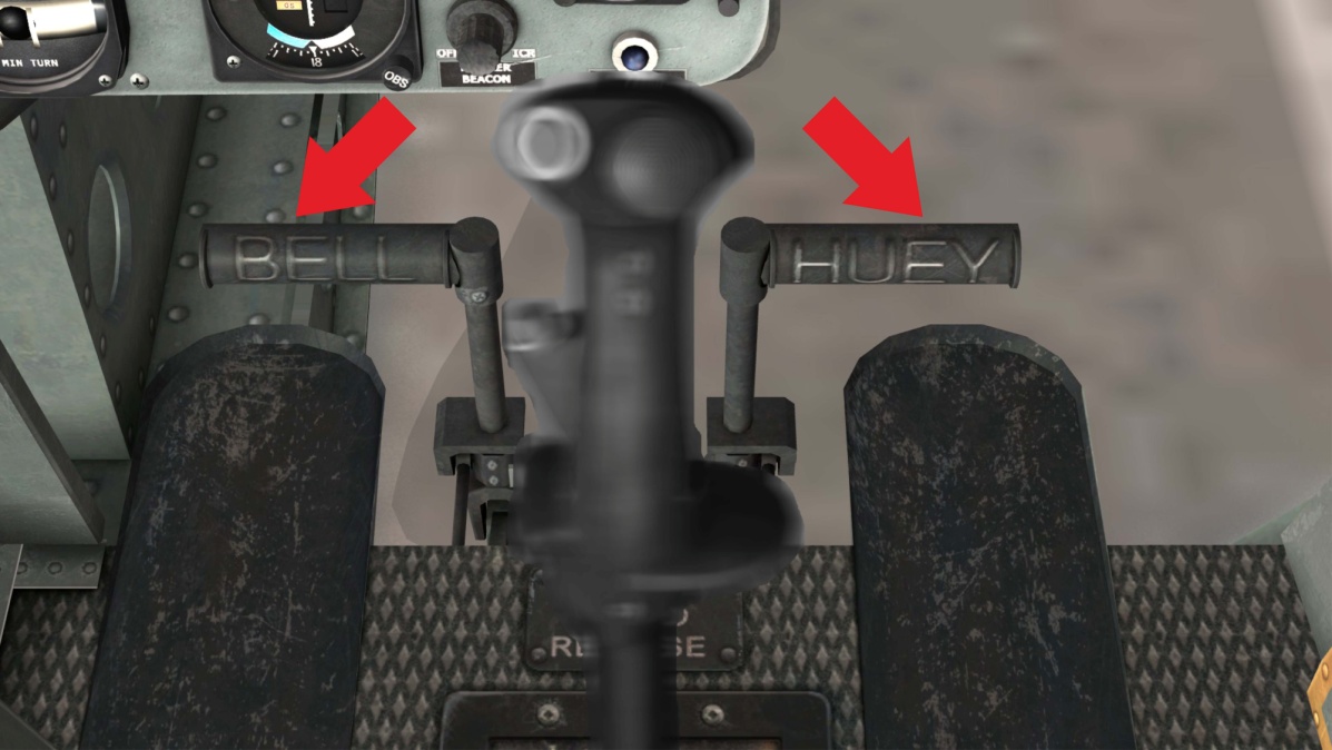
The tail rotor control system is operated by pilot/copilot anti-torque pedals. Pushing a pedal will change the pitch of the tail rotor blades, resulting in directional control. Pedal adjusters are provided to adjust the pedal distance for individual comfort. A force trim system is connected to the directional controls.
Force centering devices are incorporated in the cyclic controls and directional pedal controls. These devices are installed between the cyclic stick and the hydraulic servo cylinders, and between the anti-torque pedals and the hydraulic servo cylinder. The devices furnish a force gradient or "feel" to the cyclic control stick and anti-torque pedals. A FORCE TRIM ON/OFF switch is installed on the miscellaneous control panel to turn the system on or off. These forces can be reduced to zero by pressing and holding the force trim push-button switch on the cyclic stick or moving the force trim switch to OFF.
The power system of the UH-1H consists of a single Textron Lycoming T53-L-13B turboshaft engine with a maximum output power of 1100kW/1400 hp.
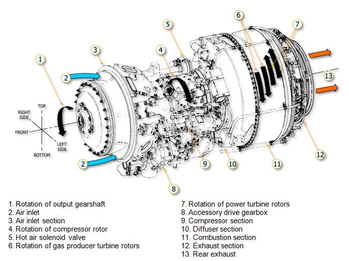
The fuel control assembly is mounted on the engine. It consists of a metering section, a computer section and an overspeed governor.
The metering section is driven at a speed proportional to N1 speed. It pumps fuel to the engine through the main metering valve or if the main system falls through the emergency metering valve which is positioned directly by the twist grip throttle.
The computer section determines the rate of main fuel delivery by biasing main metering valve opening for N1 speed, inlet air temperature and pressure, and throttle position. It also controls the operation of the compressor air bleed and operation of the variable inlet guide vanes.
The overspeed governor is driven at a speed proportional to N2 speed. It biases the main metering valve opening to maintain a constant selected N2 RPM.
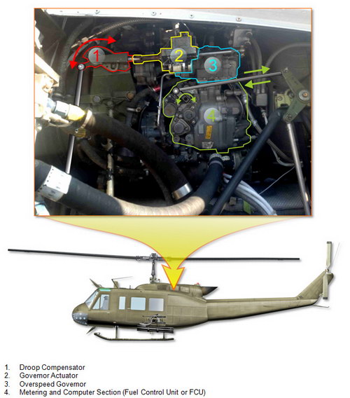
Rotating the pilot or copilot twist grip-type throttle to the full open position allows the overspeed governor to maintain a constant RPM.
Rotating the throttle toward the closed position will cause the rpm to be manually selected instead of automatically selected by the overspeed governor. Rotating the throttle to the fully closed position shuts off the fuel.
An idle stop is incorporated in the throttle to prevent inadvertent throttle closure. To bypass the idle detent press the IDLE REL switch and close the throttle.
The GOV switch is located on the ENGINE control panel. AUTO position permits the overspeed governor to automatically control the engine rpm with the throttle in the full open position. The EMER position permits the pilot or copilot to manually control the rpm. Because automatic acceleration, deceleration, and overspeed control are not provided with the GOV switch in the EMER position, control movements must be smooth to prevent compressor stall, overspeed, over-temperature, or engine failure.
Note. If GOV switch is in EMER position and throttle is full opened, main rotor rpm can exceed the limit, so pilot should control engine and rotor rpm manually by rotating the throttle twist grip.
The system consists of an engine oil tank with deaeration provisions, thermostatically controlled oil cooler with bypass valve, pressure transmitter and pressure indicator, low pressure warning switch and indicator (see Caution Lights Panel), sight gauges and oil supply return vent and breather lines. Pressure for engine lubrication and scavenging of return oil are provided by the engine mounted and engine driven oil pump.
The pilot and copilot GOV RPM INCR/DECR switches are mounted on a switch box attached to the end of the collective pitch control lever. The switches are a three-position momentary type and are held in INCR (up) position to increase the power turbine (N2) speed or DECR (down) position to decrease the power turbine (N2) speed.
A droop compensator maintains engine RPM (N2) as power demand is increased by the pilot. The compensator is a direct mechanical linkage between the collective stick and the speed selector lever on the N2 governor. No crew controls are provided or required. The compensator will hold N2 RPM to 340 RPM when properly rigged. Droop is defined as the speed change in engine rpm (N2) as power is increased from a no-load condition. It is an inherent characteristic designed into the governor system. Without this characteristic instability would develop as engine output is increased resulting in N1 speed overshooting or hunting the value necessary to satisfy the new power condition.
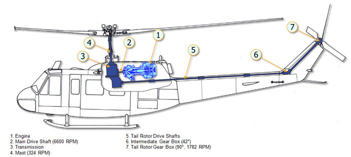
The power train is a system of shafts and gear boxes through which the engine drives the main rotor, tail rotor, and accessories, such as the DC generator and the hydraulic pump. The system consists of a main drive shaft, a main transmission, which includes input and output drives, and the main rotor mast, and a series of drive shafts with two gear boxes through which the tail rotor is driven.
The main transmission is mounted forward of the engine and coupled to the power turbine shaft at the cool end of the engine by the main driveshaft. The transmission is basically a reduction gearbox, used to transmit engine power at a reduced rpm to the rotor system. A freewheeling unit is incorporated in the transmission to provide a quick-disconnect from the engine if a power failure occurs. This permits the main rotor and tail rotor to rotate in order to accomplish a safe auto-rotational landing. The tail rotor drive is on the lower aft section of the transmission. Power is transmitted to the tail rotor through a series of driveshaft and gearboxes. The rotor tachometer generator, hydraulic pump, and main DC generator are mounted on and driven by the transmission. A self-contained pressure oil system is incorporated in the transmission. The oil is cooled by an oil cooler and turbine fan. The engine and transmission oil coolers use the same fan. The oil system has a thermal bypass capability. An oil level sight glass, filler cap, and magnetic chip detector are provided. A transmission oil filter is mounted in a pocket in the upper right aft corner of sump case, with inlet and outlet ports through internal passages. The filter incorporates a bypass valve for continued oil flow if screens become clogged. The transmission external oil filter is located in the cargo-sling compartment on the right side wall, and is connected into the external oil line. On Helicopters equipped with the Oil Debris Detection System (ODDS), a full flow debris monitor with integral chip detector replaces the integral oil filter. A bypass valve is incorporated, set to open at a set differential pressure to assure oil flow if filter element should become clogged.
Normal revolution (min-1): main rotor (mast): 324, tail rotor: 1782.
