The North American F-86F Sabre is a day, clear weather, transonic fighter-interceptor with a secondary ground attack capability. The foremost US fighter of the Korean War (1950-53), the F-86 was the only Allied jet that could hold its own – and in the right hands, outmatch - the Russian-made MiG-15s over the bitterly-contested North Korean airspace known as ‘MiG Alley’.
The F-86F is armed with six .50 in/12.7 mm Colt-Browning М3 machine guns, with a rate of fire of 1100 rounds per minute and 300 rounds per gun. A game-changer at the time, the Sabre’s excellent APG-30 gunsight helped give it the edge in dogfights, enabling accurate fire at longer ranges. It can also carry two AIM-9B Sidewinder missiles. For air-to-ground strikes the F-86 can deliver up to sixteen HVAR unguided rockets or pairs of AN-M64 500lb or M117 750lb General Purpose bombs.
Powered by a single General Electric J47-GE-27 turbojet providing 5,910 lbs of thrust, the F-86F has a maximum speed of 595 knots at sea level, a rate of climb of 9,000 fpm to 49,600 feet and a combat radius of about 600 nautical miles.
Almost 10,000 were built, making the F-86 the most-produced Western jet-fighter of all time. Exported to many countries, it saw service with almost 30 air forces. It last saw action flying in Pakistani Air Force colors during the 1971 war with India.
Experience the strengths and challenges of the Sabre in combat and find out why seasoned fighter pilots often look back on it as the most enjoyable aircraft they ever flew.
Normal crew: 1
Maximum allowable gross: 20,611 lbs / 9,348 kg
Basic weight: 11,125 lbs / 5,046 kg
Useful load (with pilot 230 lbs): 6,607 lbs / 2,996 kg
Weight with payload for normal mission: 15,175 lbs / 6,883 kg
Fuel usable capacity internal (JP-4, 0.778 kg/l): 2,826 lbs / 435 gal / 1,282 kg / 1,647 l
Fuel consumption rate (for loiter at 30,000 ft, CAS 192 kts, RPM 74%, gross weight 12,296-15,138 lbs): ~1,150 lbs/h / 522 kg/h
Normal cruise speed (for maximum range at 35,000 ft, RPM 78%, gross weight 12,296-15,138 lbs): 260 kts / 482 km/h
Maximum speed at sea level: 600 kts / 1,111 km/h
Maximum speed at 33,000 feet: 313 kts / 580 km/h
Service ceiling (for weight 14,000 lbs): 52,000 ft / 15,850 m
Maximum rate of climb: 9,500 ft/min / 2,835 m/min
Maximum range: 1,395 nm / 2,584 km
F-86F Sabre can perform different combat roles that include destruction of both air and ground targets. Integral weapons and various pod-type armament make it possible to show its combat capabilities:
- 6 Colt-Browning М3 machine guns (calibre – 12.7 mm, rate of fire – 1100 rounds per minute, weapons capacity – 300 rounds per machine gun)
- 2 AN-M64 bombs
- 16 HVAR unguided rockets

The J47-GE-27 jet turbine engine installed on the F-86F was manufactured by General Electric and has a static thrust of about 6,000 pounds (2,680kgf).

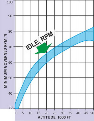
The jet turbine model is based on the simulation of the gas-dynamic duct, the condition of which is closely interrelated to the air intake, compressor, combustion chamber, turbine, and exhaust cone models of operation. In addition to this, the engine fuel control system is fully simulated. All these models interrelate with each other and this makes it possible to attain manifestation of the following features:

Fuel consumption to the engine is governed by the fuel management system (engine fuel control system) consisting of the main fuel control system and emergency (back-up) fuel control system. The emergency system is used to maintain the fuel flow to the engine in case of a failure of the main system.


