The North American F-86F Sabre is a day, clear weather, transonic fighter-interceptor with a secondary ground attack capability. The foremost US fighter of the Korean War (1950-53), the F-86 was the only Allied jet that could hold its own – and in the right hands, outmatch - the Russian-made MiG-15s over the bitterly-contested North Korean airspace known as ‘MiG Alley’.
The F-86F is armed with six .50 in/12.7 mm Colt-Browning М3 machine guns, with a rate of fire of 1100 rounds per minute and 300 rounds per gun. A game-changer at the time, the Sabre’s excellent APG-30 gunsight helped give it the edge in dogfights, enabling accurate fire at longer ranges. It can also carry two AIM-9B Sidewinder missiles. For air-to-ground strikes the F-86 can deliver up to sixteen HVAR unguided rockets or pairs of AN-M64 500lb or M117 750lb General Purpose bombs.
Powered by a single General Electric J47-GE-27 turbojet providing 5,910 lbs of thrust, the F-86F has a maximum speed of 595 knots at sea level, a rate of climb of 9,000 fpm to 49,600 feet and a combat radius of about 600 nautical miles.
Almost 10,000 were built, making the F-86 the most-produced Western jet-fighter of all time. Exported to many countries, it saw service with almost 30 air forces. It last saw action flying in Pakistani Air Force colors during the 1971 war with India.
Experience the strengths and challenges of the Sabre in combat and find out why seasoned fighter pilots often look back on it as the most enjoyable aircraft they ever flew.
The F-86, produced by the North American Aviation, is undoubtedly one of the most famous aircraft of the second half of the 20th century. It is not only famous for its outstanding performance, but also its wide use in various armed conflicts. The successful use of the aircraft during the Korean War, where the Sabre got nicknamed the MiG Killer, made the aircraft a commercial success. The F-86 was supplied to more than 30 countries and was in operational service up to the early 1970's. The F-86 won more than 900 victories in dogfights. No other jet-propelled aircraft has ever achieved that. In addition to its role as an air-to-air fighter, the Sabre was also used as a strike aircraft, reconnaissance aircraft, target aircraft, as well as a platform for testing systems and weapons. Its modifications are as follows: XF-86, YF-86A, F-86A, DF-86A, RF-86A, F-86B, F-86C, YF-86D, F-86D/L, F-86E, F-86E(M), QF-86E, F-86F, QF-86F, RF -86F, TF -86 F, YF-86H, F-86H, QF-86H. More than 9,800 Sabres were produced (of all the modifications). Follow-on updates and the perfecting of its armaments and avionics continued throughout the aircraft production period; for this reason, within the framework of one modification there are several various series. In this simulation we have modeled the F-86F modification of series 35, which is one of the latest series of the "F" modifications.
The cockpit of the F-86F series 35 was implemented with the maximum possible level of precision. The instruments, instrument panels, aircraft systems control panels, and controls were designed using high resolution textures and animations. The pilot's camera in the Sabre virtual cockpit has six degrees of freedom, which makes a player feel like they are in the real cockpit. The cockpit also supports Oculus VR.
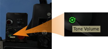
To simplify the mastering of the virtual cockpit, all the elements are equipped with cues appearing when you pass the mouse over them.

The 3D Sabre model is implemented to the same high quality standards and best traditions of our designers; it is highly detailed using multitexture maps, normal maps, and specular maps, all the control surfaces are accurately animated.
Our F-86F model is the virtual copy of this famous aircraft in the truest sense of the word. The external model and the cockpit have been scrupulously simulated. As with all of our products, a very detailed simulation of the engine and flight dynamics is also included. This allows us to attain a very close correspondence between the operational and physical characteristics and all the peculiarities of F-86F Sabre flight behaviour. Employment of all the weapon systems (machine guns, rockets, bombs) is possible during various combat missions.
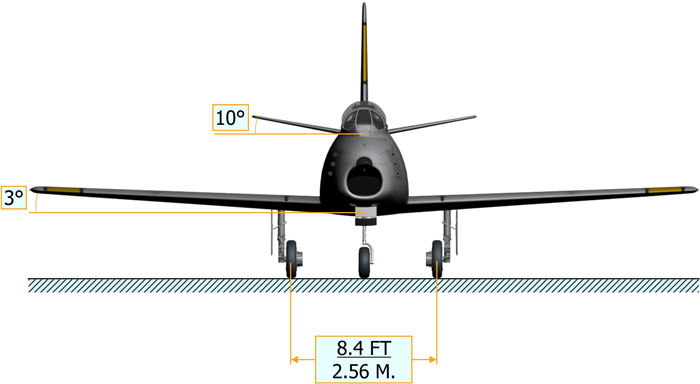
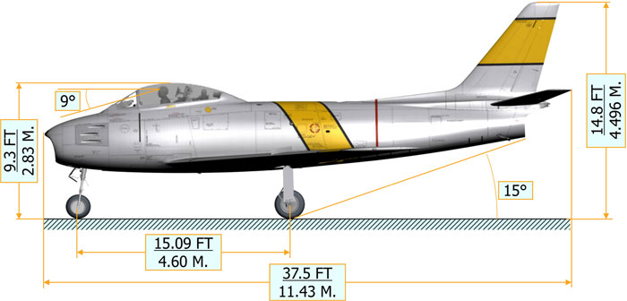
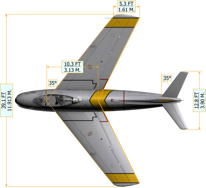
Normal crew: 1
Maximum allowable gross: 20,611 lbs / 9,348 kg
Basic weight: 11,125 lbs / 5,046 kg
Useful load (with pilot 230 lbs): 6,607 lbs / 2,996 kg
Weight with payload for normal mission: 15,175 lbs / 6,883 kg
Fuel usable capacity internal (JP-4, 0.778 kg/l): 2,826 lbs / 435 gal / 1,282 kg / 1,647 l
Fuel consumption rate (for loiter at 30,000 ft, CAS 192 kts, RPM 74%, gross weight 12,296-15,138 lbs): ~1,150 lbs/h / 522 kg/h
Normal cruise speed (for maximum range at 35,000 ft, RPM 78%, gross weight 12,296-15,138 lbs): 260 kts / 482 km/h
Maximum speed at sea level: 600 kts / 1,111 km/h
Maximum speed at 33,000 feet: 313 kts / 580 km/h
Service ceiling (for weight 14,000 lbs): 52,000 ft / 15,850 m
Maximum rate of climb: 9,500 ft/min / 2,835 m/min
Maximum range: 1,395 nm / 2,584 km
F-86F Sabre can perform different combat roles that include destruction of both air and ground targets. Integral weapons and various pod-type armament make it possible to show its combat capabilities:
- 6 Colt-Browning М3 machine guns (calibre – 12.7 mm, rate of fire – 1100 rounds per minute, weapons capacity – 300 rounds per machine gun)
- 2 AN-M64 bombs
- 16 HVAR unguided rockets

The J47-GE-27 jet turbine engine installed on the F-86F was manufactured by General Electric and has a static thrust of about 6,000 pounds (2,680kgf).

The jet turbine model is based on the simulation of the gas-dynamic duct, the condition of which is closely interrelated to the air intake, compressor, combustion chamber, turbine, and exhaust cone models of operation. In addition to this, the engine fuel control system is fully simulated. All these models interrelate with each other and this makes it possible to attain manifestation of the following features:
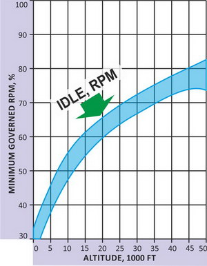
Fuel consumption to the engine is governed by the fuel management system (engine fuel control system) consisting of the main fuel control system and emergency (back-up) fuel control system. The emergency system is used to maintain the fuel flow to the engine in case of a failure of the main system.

Fuel in the aircraft is kept in four tanks. Two fuel tanks are in the fuselage and one fuel tank is inside each half-wing. In order to increase the fuel load, external fuel tanks may be installed on the wings: two tanks under each half-wing. Fuel tank pylons located closer to the fuselage have a capacity of 450 liters (120 gallons). The tanks with a capacity of 750 liters (200 gallons) are mounted on special pylons located further from the fuselage.

The DCS: F-86F is equipped with both DC and AC electrical systems.
Direct-Current (DC) power supplies:
Alternating-Current (AC) is provided by a single-phase (115V, 400Hz) and two three-phase (36V, 400Hz) inverters.
DCS: F-86F Sabre has three separate hydraulic systems of constant pressure: utility hydraulic system, flight control normal hydraulic system, and flight control alternate hydraulic system.
The utility hydraulic system is completely independent of two boost systems. Moreover, it has a hydraulic accumulator for emergency extension of the nose landing gear.
The utility hydraulic system provides:

There are two independent boost hydraulic systems: normal hydraulic system and alternate hydraulic system are installed in the F-86F flight control system.
The boost hydraulic systems are intended to control ailerons, horizontal tail and elevator (they transfer the governing input from the control stick to actuation hydraulic drives).

The DCS: F-86F control system has a number of unique features:

Thus, any aerodynamic loads are not tranferred to the control stick. However the pilot still feels input forces on the control stick. This is achieved by introducing roll and pitch feel spring mechanisms into the aircraft control system.
In our simulation, just like in the real F-86F, the pilot's health state in all the range of altitude and speeds is provided by two systems:
Both systems use hot air from behind the engine compressor, and for this reason they are combined into one environment control system.

Pressure in the cockpit is maintained by the airflow from vent openings and is set by a differential pressure regulator depending on altitude. The greater the altitude, the more differential pressure (altitude difference) in the pilot's cockpit to maintain the normal vital functions.
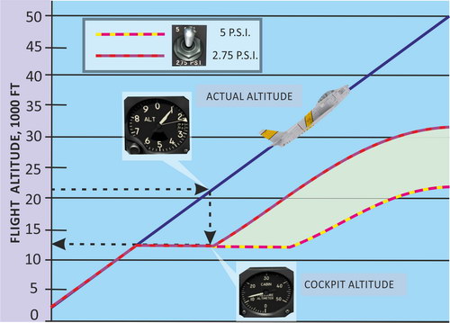
Thus, if a player does not observe the environmental control system settings, a "loss of consciousness" and "windshield weeping" may occur.
The flight dynamics model describes the aerodynamic performance of the F-86F with the J47-GE-27 engine and the "6-3" wing of increased area without a drooping slat.
During the simulation, complex calculations of the characteristics of the aircraft constituent elements are performed taking into account their mutual influence in all the range of local angles of attack and of sideslip (including beyond stall angles as well), local ram-air flows and Mach numbers taking into account control deflections, and the level of destruction of certain elements of airframe and control surfaces.
As a result of the simulation, a series of aerodynamic peculiarities of the model should be noted, which according to the available documentation, are typical for the real aircraft.
Between high indicated airspeed and Mach number (within the flight restrictions), a series of unique characteristics manifest themselves in aircraft behaviour.
Starting at Mach 0.9, unintentional roll (wingheaviness) (to the left or to the right) manifests itself and it strengthens as the Mach number increases up to its limit values. Appearance of this wingheaviness is associated with the geometric asymmetry of half-wings and also with their unequal flexural-and-torsional load-deflection curves. The wingheaviness is accompanied by a significant decrease of the aileron effectiveness related to wave effects and wing deformation during their deflection.
The airflow compressibility influence on longitudinal flying qualities at high speeds remains insignificant up to Mach 0.95. With further increase of the Mach, the aircraft demonstrates excessive tendency to pitching-up, the compensation of which requires additional pushing force on the control stick.
Due to the above-mentioned peculiarities of the aircraft behaviour, the indicated air speed is restricted to 600 knots.
Reason: Developing wing heaviness at considerable decrease of the aileron effectiveness (at high values of the Mach number) and additional wing bending and wing torsion under the action of the airflow at aileron deflection.
Acceleration higher than the value of Mach 0.93 is only possible when descending.
At all speeds, the aircraft is sensitive to longitudinal control. This is especially true between Mach 0.8-0.9 and indicated air speed values over 500 knots.
The aircraft has relatively high maneuverability at all speeds. Here it should be taken into account that in order to execute most manoeuvers, a slight tail unit deflection (especially pitching displacement) is required.
However, at medium and low altitudes and indicated air speed over 500 knots, roll control becomes slow. This is due to the wing bending and wing torsion. Simultaneously, the aileron effectiveness decreases, which makes it difficult to maneuver at speeds over 550 knots.

A characteristic feature of piloting is hyperreaction to longitudinal input of the control stick. This feature may lead to a stall of the aircraft or to exceed the operational glideslope.
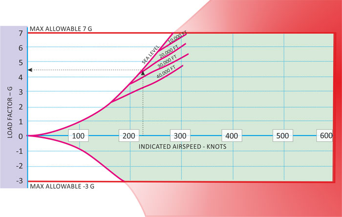
The warning factor of exceeding the maneuver limitation is the starting wing stalling accompanied by shaking and departure tendency. Piloting at the shaking mode is possible but requires particular attention to the aircraft behaviour and timely decrease of the g force (angle of attack) at a decrease of the indicated air speed of the flight.
Stalling in level flight occurs without warning shaking (typical for the unslatted F-86) to any side with a nosing down of the aircraft. Simultaneously, roll reversal manifests itself to the control stick input. The sign of upcoming stall may be developing includes vibrations, banking while holding the aircraft horizontally, and speed drop.
During landing, it is necessary to observe the recommended speed to prevent stalling speed in various configurations.
Stalling in level flight occurs at lower speeds based on configuration. This owes to the fact that in the flight at positive angles of attack there is a vertical component of the engine thrust decreasing value of the required lift and, consequently, value of the required angle of attack.
The presence of external loads increases the stalling speed approximately by 10 knots.
At vigorous pull-up command (due to the high controllability in pitch) can induce departure mode without the warning shaking with abrupt wing drop.
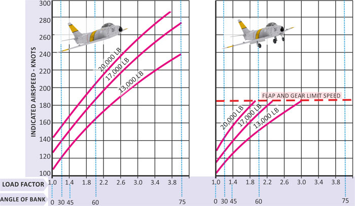
Recovery from a stall is performed by a slight pushover and increase of RPM.
An aircraft enters a spin in any configuration and in all the flight speed range up to the Mach number of 0.9. In any case, the spin is the result of stall at excessing available g forces during maneuvering or at the drop of speed lower than the allowable one for the current weight and flight configuration of the aircraft.
With the correct spin recovery technique taken into account and available altitude, aircraft recovery is possible from any kind of spin.
Upon entering a spin, the aircraft nose goes below the horizon to the angle of 50-75 degrees with a slow rotation. When the rotation rate increases, the aircraft nose goes up almost to the horizon. The first spin turn occurs approximately in 5-8 sec. with the altitude loss of 500-600 feet. During the next turn, the rotation rate increases with the diminution of amplitude of nosing up to the horizon and an increase of the climb angle to the vertical one.
At the same time, with each next turn the altitude loss increases and may reach 2.000 feet per turn.
Typically, the aircraft falls into a right-hand spin.
A spin with increased engine thrust is characterized by smaller climb angles and higher rotation rate.
A spin with minimal thrust or without power is characterized by a steeper (up to 90 degrees in the process of development) trajectory.
The spin quality does not change with the speedbrakes deployed.
In landing configuration, the spin peculiarity is smaller altitude loss at first turns.
With external fuel tanks, a change of spin direction may occur both upon entering the spin and after several turns.
Spin recovery occurs when the controls are set to their neutral position. As a rule, simultaneously, the aircraft recovers from the spin on its own with some delay.
For a controlled spin recovery, it is recommended:
If an aircraft carrying external loads has entered a spin and it is impossible to recover from the spin in the course of one or one and a half turns, then it is recommended to jettison all external loads and recover the aircraft from the spin according to the normal procedure.
It is forbidden to execute the following maneuvers:


