
|
|
|

|
|
23 January 2026
Dear Fighter Pilots, Partners and Friends,
Since the DCS: MiG-29A Fulcrum Early Access release, we’ve focused on refining sensors and navigation, improving radar/Infrared Search and Track (IRST) performance (including COOP), and finalizing ground-attack modes and weapons. We also continue to add some highly detailed features to the external model and cockpit. Based on community reports and pilot testimony, we’ve also improved the SPO-15LM, radar behavior, and more. Please read below.
Last week, Matt “Wags” Wagner released an instruction video on the operation of the Radar and Infrared Search and Track Cooperative mode. The next Fulcrum instruction video will be on the Track-While-Scan Feature (TWF) mode. Coming soon!
Heatblur Simulations recently shared an early look at work in progress on the DCS: A-6E radar, including the Terrain Clearance mode. This is a key capability for the Intruder, and the team is steadily bringing it to life, focusing on authenticity, usability, and the kind of low-level confidence that defines the aircraft’s all-weather strike role.
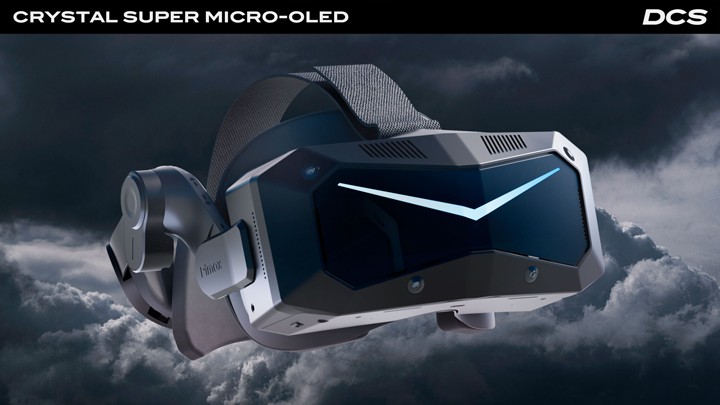
Time is running out to receive 40,000 ED Miles (worth $40 in the DCS e-shop) when you buy the new Crystal Super micro-OLED VR headset. Go to Pimax.com and use the code DCS40K by the end of February 6th to claim yours!
Thank you for your passion and support.
Yours sincerely,
Eagle Dynamics
|
MiG-29A Fulcrum
Development Update
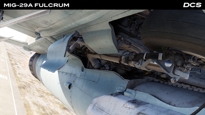
Since the release of the DCS: MiG-29A, the team has focused mainly on correcting errors and improving the sensors and systems including the Radar/IRST suite, as well as ground attack weapons and delivery modes. We are also refining the operation of the FCR (Fire Control Radar) and IRST in COOP mode and fixing errors in INS and navigation modes.
After the initial release of DCS MiG-29, we received some excellent community feedback pertaining to limitations of SPO-15LM that did not align with pilot testimony. In particular, the inability to receive signals in the forward hemisphere while the onboard radar is transmitting. We re-evaluated the technical documentation and analysed signals from the N019 Pulse-Doppler radar to the SPO-15LM, and we determined that while full synchronization is not possible due to hardware limitations, the actual blocking logic is software-controlled. The full report is available here: Summary of SPO-15LM synchronization systems. Since the report was released, we have received additional pilot testimony and training materials that are being analysed.
We have made certain improvements to the simulation like the ability to force SPO-15LM launch warnings for specific combinations of threat types and their operating mode (search or track) via the DTC interface. Additionally, several immediate issues were fixed, and the radar parameter database was updated with the most notable changes being to the Ropucha and Tu-95 radar reception.
Current tasks:
- Development of the concept for the command radio control line.
- Refinement of the logic for data processing and updating in the Track-While-Scan Feature (TWF) mode.
- Refinement of the sensitivity for the photodetector for IRST.
- The art team continues to improve the cockpit elements and exterior models, as well as the pilot model. This includes service hatches, more detailed countermeasures dispensers, more detailed leading edge extension intakes, and new liveries. We are adding new models of missile rails and a dual bomb rack.
- Once the external model is finalized, the template will be made available.
- As resources become available, we plan to refine the Automatic Control System and also improve the IFF.
|
Heatblur A-6E Dev Report
Terrain Clearance Mode
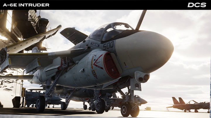
Heatblur Simulations is proud to share some work in progress on the DCS: A-6E's radar and Terrain Clearance mode.
Since we are not blessed with the eyes of a chameleon, the Bombardier/Navigator's Radar Display and the Pilot's Analog Display Indicator (ADI) have been combined into a single debug windows that allows us to see them side by side, along with the terrain outside the cockpit for comparison. Please note that the cockpit model is a placeholder and does not represent the final product.
In the included example, the radar is in Terrain Clearance (TC) mode that restricts the display to ~8.5nm and the minimum scan angle to ~60°. The radar's primary purpose is to drive the ADI display in this mode.
During normal flight, the pilot's ADI is similar to the F-14 Tomcat’s VDI; however, when TC mode is selected, it displays a 53° (horizontal) x 26° (vertical) pictorial representation of the terrain ahead of the aircraft based on the data supplied by the radar.
On the ADI, we see the black Horizon Line and Fiducial Markers that help mark our pitch and bank attitude. In the center are the Steering Symbol and Flight Path Lines, currently locked to the aircraft heading. Behind this symbology are displayed ten discrete bands, each representing a range contour, from ~0.25nm out to 8.5nm. Bands 1 and 7 are permanently coded with range coding bars for identification, while bands 3-6 may be selected for coding - that is, to display the vertical black bars - based on pilot input. In the example below, the pilot selects band 4 for coding.
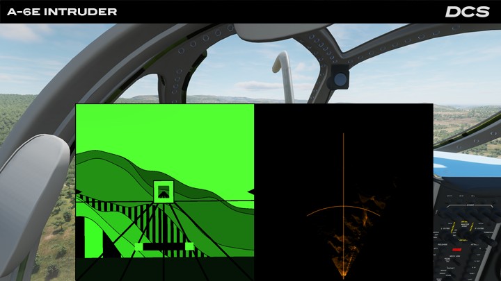
The pilot maintains clearance over the terrain by flying the aircraft so that the Offset Impact Bar (black and green, fixed near the bottom of the screen) is situated above one of the coded bands 3-6. The selected band determines the clearance height and smoothness of the ride.
Finally, at the bottom of the screen is the dark green Altitude Curtain. This moves up and down the screen relative to the Horizon Line to represent the radar altitude. Its range is not linear and does not correspond to the terrain contour bands, but serves as a visual guide to aid piloting.
More symbology remains to be added, but hopefully, this demonstration gives some insight into the progress on a rather unique feature of the DCS A-6E Intruder.
See more screenshots here!
The Heatblur Team
|
Pimax
Crystal Super micro-OLED Promotion
Get 40,000 Bonus ED Miles with the New Crystal Super micro-OLED
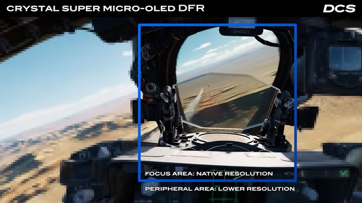
The Crystal Super micro-OLED builds on the original Crystal Super platform by upgrading it with dual 4K Sony micro-OLED panels and Pimax’s ConcaveView pancake optics - bringing sharper visuals, deeper blacks, and a wide field of view to your DCS cockpit.
Use code DCS40K at checkout to claim 40,000 ED Miles (USD $40 value) with your purchase.
Why Choose the Pimax Crystal Super micro-OLED?
- 27 million pixels (3840 × 3552 per eye) deliver ultra-sharp visuals, precise contrast, and clean edges around aircraft, gauges, and terrain.
- In low light missions, the micro-OLED’s zero-backlight design means black pixels stay truly black for pure realistic darkness.
- The three-layer ConcaveView pancake lenses in the Super micro-OLED give the widest field of view of any micro-OLED VR headset at 116° horizontal FOV.
- Built-in eye-tracking means QuadViews Dynamic Foveated Rendering works out of the box - boosting performance by up to 50% with no external tools.
- Integrated audio and a balanced ergonomic backstrap ensure comfort for long DCS sorties, while a cabled DisplayPort 1.4a connection ensures visually lossless clarity.
- Four onboard SLAM cameras provide full inside-out tracking - no base stations are needed.
Claim your 40,000 ED Miles bonus with the Crystal Super micro-OLED using code DCS40K: https://pimax.com/pages/dcs/?ref=DCS40
If you have already purchased your Crystal Super micro-OLED and wish to receive your ED Miles credit, you will soon receive a unique code from Pimax that should be entered into the My Miles section of the DCS website.
For VR tips and recommended settings per GPU, visit the Pimax section of the DCS Forum.
Thank you again for your passion and support,
Yours sincerely,
Eagle Dynamics
|
|
A confirmation email has been sent to your E-mail
| |
|
|
|


