DCS: Black Shark 2 ist eine Simulation des russischen Kampfhubschraubers Ka-50. DCS: Black Shark 2 ist eine stark verbesserte Version des ersten "DCS: Black Shark" und beinhaltet viele neue Verbesserungen.
Der Ka-50 "Black Shark" ist ein einzigartiger, einsitziger, russischer Kampfhubschrauber, der u. a. in Kampfeinsätzen im Nordkaukasus eingesetzt wurde. Er kombiniert einen leistungsstarken Koaxialrotor mit einer tödlichen Bewaffnung. Die Bewaffnung umfasst gelenkte Raketen, ungelenkte Raketen, Bomben, Geschützbehälter und ein 30-mm-Bordgeschütz. Eine Besonderheit des Ka-50 ist, dass sich der Pilot mittels Schleudersitz retten kann.DCS: Ka-50 Black Shark ist die Simulation des russischen Kampfhubschraubers Ka-50 und ist der erste Titel einer neuen Simulationsreihe von Eagle Dynamics und The Fighter Collection: DCS. DCS: Ka-50 Black Shark folgt der herausragenden Tradition von Eagle Dynamics und bietet ein noch realistischeres Simulationserlebnis als sein Vorgänger LockOn: Flaming Cliffs.
DCS: Ka-50 Black Shark bietet in Bezug auf Flugdynamik, Instrumentenmodellierung, Avioniksysteme und Waffensysteme einen noch nie dagewesenen Grad an Realismus. Die künstliche Intelligenz von Bodenfahrzeugen und Hubschraubern wurde ebenso wie die Waffenmodellierung dramatisch verbessert. Mit dem neuen Missionseditor kann der Benutzer auf einfache Weise Missionen und Kampagnen erstellen. Ein neues Kampagnensystem ermöglicht es der Frontlinie auf dem Schlachtfeld, sich je nach Erfolg oder Misserfolg der Mission zurück oder vor zu bewegen. Aufgrund der erhöhten Flexibilität von DCS World werden in Kürze weitere Flugzeuge und Hubschrauber folgen.
Das Flug- und Systemmodell wurde mittels folgenden Methoden implementiert.
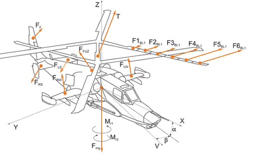
Zur Berechnung der Flugbahn des Hubschraubers wurden Gleichungen der Starrkörperdynamik verwendet. Im Wesentlichen bedeutet dies, dass alle externen Kräfte und Kraftmomente verwendet werden, um die Position und Rotation eines Körpers im 3D-Raum zu berechnen.
Die aerodynamischen Eigenschaften des Ka-50-Flugwerks ergeben sich aus seinen Sub-Elementparametern: Rumpf, Flügel, Leitwerk und Fahrwerk. Jedes dieser Elemente hat seine eigene Position und Ausrichtung innerhalb des lokalen Koordinatensystems der Flugzeugzelle und jedes hat seine eigenen aerodynamischen Eigenschaften. Jedes Unterelement wird durch unabhängige Diagramme der Auftriebsbeiwerte, des Beschädigungsgrades, der die Auftriebseigenschaften beeinflusst sowie der Schwerpunktlage und der Trägheitseigenschaften berechnet. Aerodynamische Kräfte, die auf jedes Unterelement der Flugzeugzelle wirken, werden separat in ihrem eigenen Koordinatensystem unter Berücksichtigung der lokalen Fluggeschwindigkeit des Unterelements berechnet.
Kontakte mit dem Boden und externen Objekten werden auf der Grundlage eines starren Kontaktpunktsystems modelliert.
Das Fahrwerk wird als separate Fahrwerksarme modelliert, die jeweils aus einem Rad und einem asymmetrischen Stoßdämpfer bestehen. Das Bugrad ist selbstausrichtend, basierend auf einwirkenden äußeren Kräften. Ein solches Modell ermöglicht die Modellierung eines realistischen Verhaltens einschließlich der Entwicklung von Flatter-Effekten bei hohen Geschwindigkeiten. Das Ein- und Ausfahren des Fahrwerks kann zu einer Schwerpunktverschiebung führen. Bei der Modellierung des Fahrwerksbetriebs werden die kinematischen Eigenschaften des Fahrwerks sowie externe und hydraulische Kräfte berücksichtigt. Das Ergebnis ist ein sehr realistisches Verhalten unter allen Bedingungen.
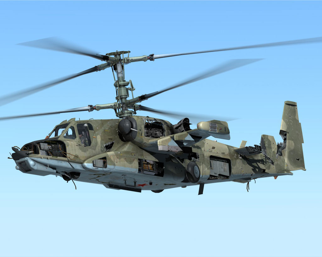
Das Schadensmodell basiert auf aerodynamischen und starren Kontaktkräften. Schäden an Flugzeugkomponenten, Fahrwerk, Rädern, Sensoren und Geräten werden alle berücksichtigt. Jegliche Schäden wirken sich auf die physikalischen und funktionellen Eigenschaften des Hubschraubers aus und führen zu einer Änderung des Schwerpunktes.
Das Rotormodell des Ka-50 Black Shark ist revolutionär unter den Hubschraubersimulatoren. Es basiert auf einem gemeinsamen Modell jedes Blattes mit seiner eigenen komplexen Bewegung relativ zur Rotorachse und mit schlagenden (horizontal) und schwenkenden (vertikal) Gelenken. Jedes Blatt ist in mehrere Segmente unterteilt, von denen jedes seinen eigenen Luftgeschwindigkeitsvektor hat, der auf seiner Ausrichtung, Anstellung und der induzierten Geschwindigkeit am aktuellen Rotorabschnitt basiert. Die induzierte Geschwindigkeit wird berechnet, indem die Gleichungen auf der Grundlage der gleichzeitigen Anwendung des Bewegungsgrößentheorems und der Blattelementmethode gelöst werden. All dies erzeugt eine natürliche Helikopterdynamik wie z. B. konische Rotorneigung im Vorwärtsflug (Schwingungen im Schwebeflug mit neutralem Steuerknüppel, der Bewegungsweg für die zyklische Steuerung nimmt entsprechend der Fluggeschwindigkeit zu), Leistungsüberschuss nach dem Übergang vom Schwebeflug in den Vorwärtsflug, Bodeneffekt (über geneigter Oberfläche oder in der Nähe von Bodenobjekten), "Wirbelring"-Phänomene, Strömungsabriss der Blätter, Überschneidung der Blätter (Kollision). Im Falle von Einzelblattschäden werden natürlich entsprechende Dynamiken als Teil des Gesamtrotormodells modelliert.
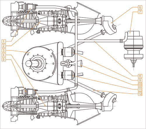
Das Ka-50-Triebwerk besteht aus einem Getriebe mit Freilaufkupplungen, zwei TV3-117VMA-Turbowellentriebwerke mit elektronischen Reglern, einem Hilfsaggregat (APU) und einem Turbogetriebe.
Zum ersten Mal in der Geschichte der Flugsimulation basiert das Triebwerksmodell auf einem detaillierten physikalischen Modell eines Turbowellentriebwerks als ein System von separaten Komponenten des gasdynamischen Triebwerkssystems: Triebwerkseinlass, Verdichter, Brennkammer, Hochdruckturbine und Nutzturbine mit Triebwerksabgasen.
Das Modell entspricht dem realen Triebwerk in allen Betriebsarten in Bezug auf Ausgangsleistung, Beschleunigung, Kompressordrehzahl, Abgastemperatur (EGT) und Kraftstoffverbrauch in Abhängigkeit von der Umgebungslufttemperatur und dem Umgebungsdruck. Der Betrieb von Zapfluftventilen wird für das Antiblockiersystem des Kompressors, das Enteisungssystem des Motors und den Staubzyklon modelliert. Durch Reduzierung des Luftstroms durch das Triebwerk erhöhen diese Vorrichtungen die EGT und senken die Startleistung des Triebwerks. Die Verschlechterung der Parameter der Treibwerkskomponenten wird im Modell innerhalb der Lebensdauer oder bei Überschreitung der Betriebsgrenzen des Start- und Notstrombetriebs oder bei Leistungsverlust mit EGT-Überschreitung umgesetzt.
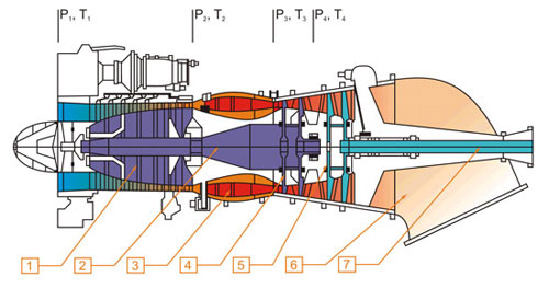
Das durch Vereisung verursachte Verdichter-Abwürgen wird so modelliert, dass dies zu Leistungsverlust, EGT-Erhöhung, Verdichter-Strömungsabriss und Flammabriss des Motors führt. Der Flammabriss wird durch die Berechnung des Luft-Kraftstoff-Verhältnisses in der Brennkammer modelliert.
Das Triebwerkssteuerungssystem besteht, wie im wirklichen Leben, aus einem Drehzahlregler für den Turboverdichter (Gasgenerator- GG), einem Drehzahlregler für die Leistungsturbine, automatischen Geräten zum Anlassen und Beschleunigen des Triebwerks, einem elektronischen Regler (EEG), der die maximale EGT begrenzt und die Drehzahl der Leistungsturbine überwacht/begrenzt. Abgesehen von der direkten Triebwerkssteuerung umfasst das Steuersystem den Start-Zyklus der APU, der Haupttreibwerke und des Turbogetriebes, Testgeräte für Triebwerk- und Triebwerkssteuerung, wie z. B. Triebwerk-Fehlstart, Triebwerkentlüftung (Kurbelwelle), EEG-Test, Neueinstellung des Drehzahlreglers des Rotors (Leistungsturbine) und vieles mehr.
Das Hydrauliksystem umfasst alle Servo-Booster, Akkumulatoren, Tanks und Boost-Pumpen. Wie im realen System ist es in ein Hauptsystem und ein gemeinsames System unterteilt, die jeweils über eigene Leitungen, Pumpen und Verbraucher verfügen. Im Modell des Servoverstärkers wird die Verschiebung der Ausgangsleistungsstange in Abhängigkeit vom Flüssigkeitsdruck (und der Position des Wahlventils) zusammen mit externen Faktoren wie Gelenkmomenten, Stützreaktionen usw. berücksichtigt. Der Systemdruck wird durch die Ladung in den Akkumulatoren in Abhängigkeit von der Förderleistung der Pumpen und dem Verbrauch der Verbraucher sowie von Schadensleckagen bestimmt.
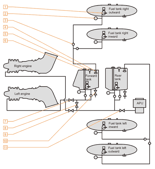
Das Treibstoffsystem des Hubschraubers umfasst Treibstofftanks, Treibstoffleitungen, Druckpumpen und Ventile. Der Treibstoffverbrauch führt zu einer Veränderung der Schwerpunktlage innerhalb der zulässigen Betriebsgrenzen. Das Treibstoffsystem wird vollständig vom Cockpit aus vom Piloten gesteuert.
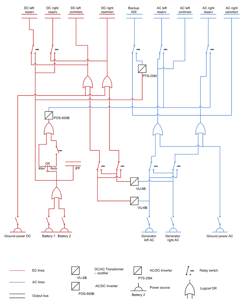
The electrical system includes:
The Ka-50 electrical power generation system provides AC and DC power to the primary and emergency buses and distribution assemblies. This power supply is used to run avionics systems, internal and external lighting, hydraulic, fuel systems control and monitoring, engines, and auxiliary power unit start up systems. When on the ground, an external power cart can be used as an alternate power source. In addition to onboard power generation capability, the Ka-50 also includes batteries that electrical power can be drawn from.
The Alternating Current System
The primary electrical system is fed by alternating current (AC) 115/200 V, 400 Hz generators. This supply is further divided into left and right systems on independent channels to provide system redundancy. Generator operation is dependent upon the left and right engines being active as each engine contains a gearbox that runs a generator. The left channel systems can be powered by the right generator and the right channel systems are powered by the left generator. In the event of both generators becoming inoperative, a back-up, static DC to AC inverter can take over power to the most important systems and direct current will trigger the in-flight warning system.
The Direct Current System
Systems requiring direct current (DC) power are supplied at 27V by use of AC to DC transformer-rectifiers. Transformer-rectifiers are active while the generators are in operation. If one of the transformer-rectifiers is switched off though, systems will be switched to the operating transformer-rectifier. If both transformer-rectifiers and/or generators are off-line, the most important avionics systems will be switched to emergency DC power.
Damage to the electrical generation system is also manifested in the visual damage model of the Ka-50. An event-oriented approach is implemented such that a loss in electrical power to systems will have a cascade effect. This specifically means that the loss of one electrical system will have repercussions affecting linked elements of the electrical system.
Although a highly detailed flight manual will be provided with DCS: Black Shark, the following provides you with a small sampling of the avionics systems modeled in our simulation of the Ka-50. Piloting, navigation, targeting and defensive systems and included in this overview.
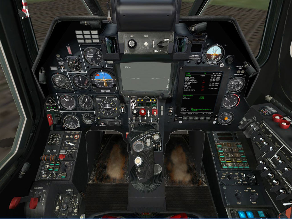
The Ka-50 cockpit instruments are generally traditional electro-mechanical gauges that are mounted on the front dash and side / back panels. These instruments are divided into three general groups: flight control, engine control/monitoring and systems control. Other cockpit interfaces include traditional switches, dials and multiple-position switches. Additionally, the Ka-50 has multiple banks of warnings lights and cockpit illumination controls.
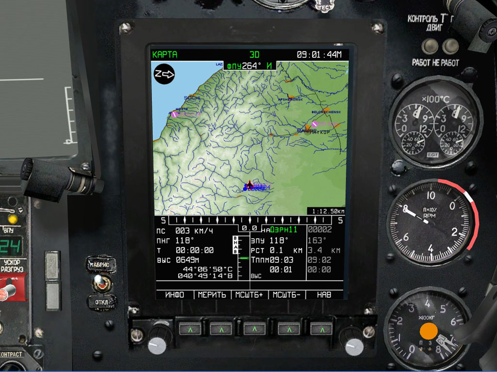
The ABRIS panel is a multi-function display that allows the pilot to perform the following tasks:
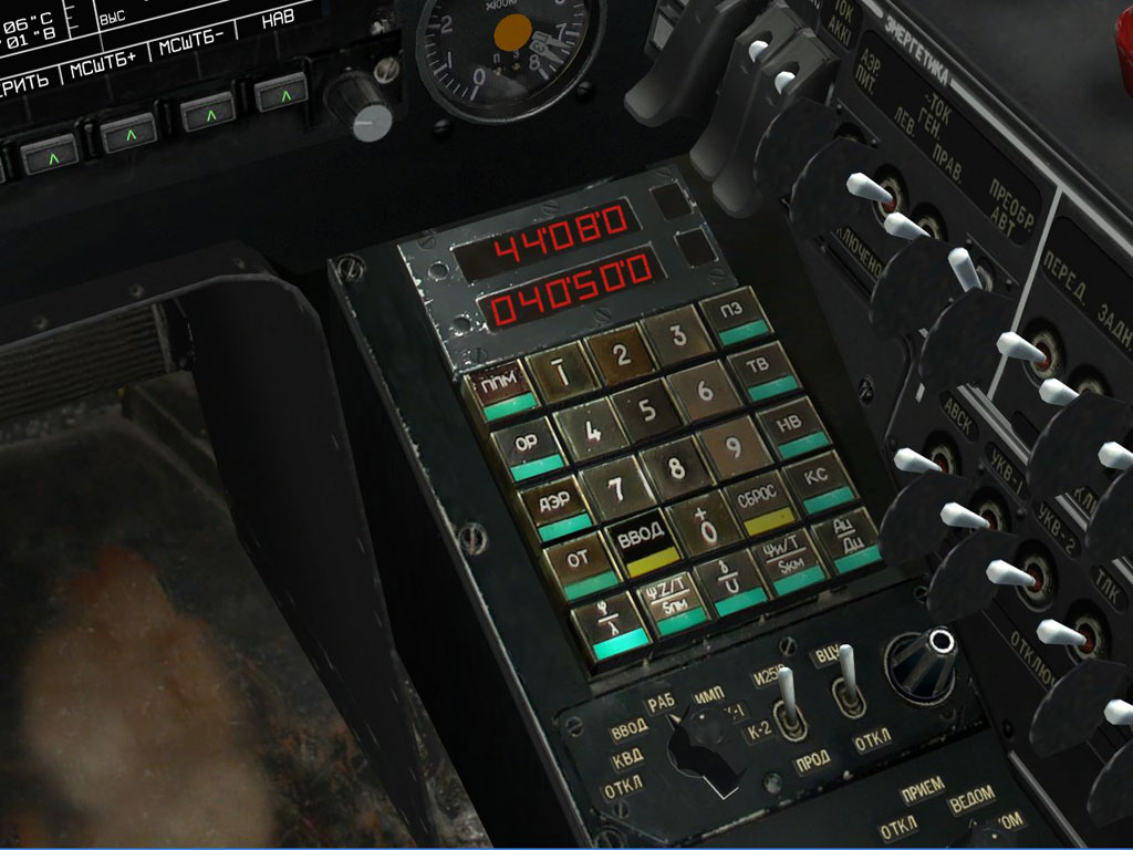
The targeting-navigation system is designed to integrate combat, navigation and flight tasks by processing both digital and analog information. «Rubicon» is integrated with the «Shkval» targeting system, airborne information display system and weapon control system.
«Radian» is a sub-system of «Rubicon» that helps automate flight navigation. «Radian» can store information in its memory such as coordinates for two airfields, six waypoints of a flight plan, ten operative targets, and four reference points.
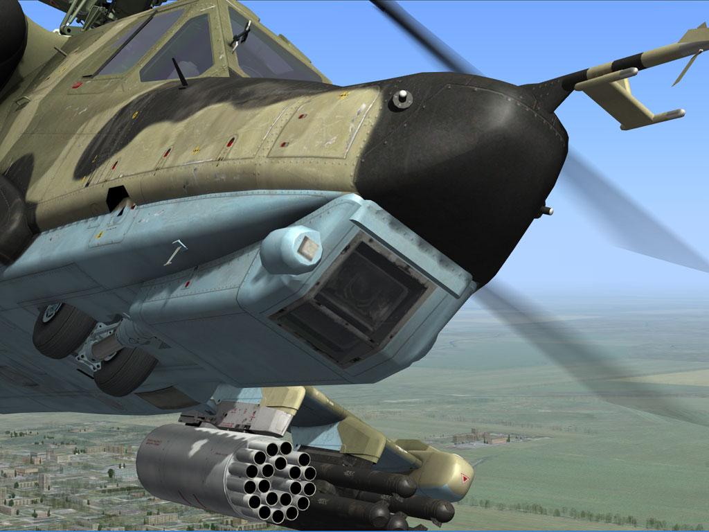
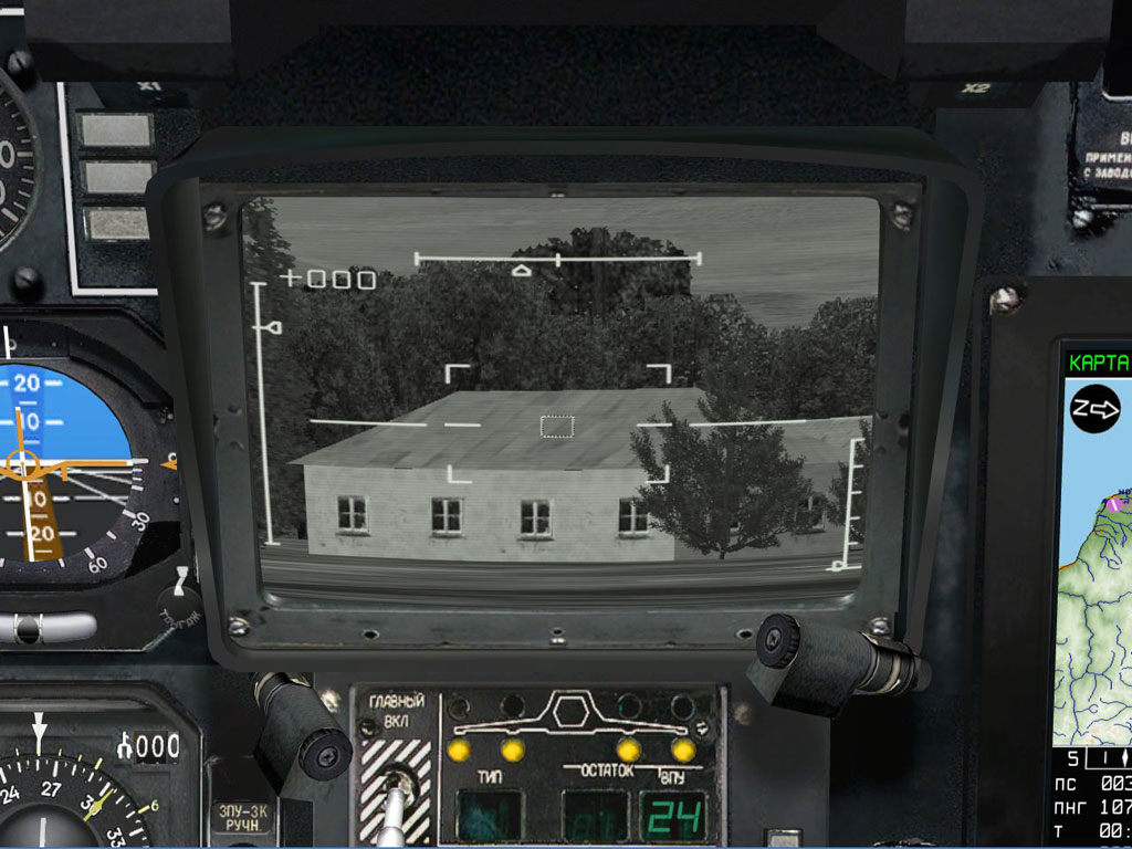
The «Shkval» system consists of a television camera combined with a laser range-finder and laser illumination designator to guide the anti-tank missile system.
The «Shkval» system can be ground-stabilizing and is capable of auto-tracking a designated target. There are two Fields Of View (FOV) levels: Wide FOV with a 6x magnification and narrow FOV with a 22x magnification. FOV gimbal suspension limits are: ±35° in azimuth and +15° to -80° in elevation.
The video picture is shown as a gray-scale image on the IT-23VM TV monitor.
The «Shkval» can be set to scan for targets automatically and the angular rate of scan can be manually be set by the pilot while in the cockpit.
To slew the «Shkval» camera, the pilot uses a small mini-stick on the helicopter cyclic.
The «Ranet» information display system is designed for processing and displaying flight, navigation and targeting information on the heads-up display and the IT-23 video indicator.
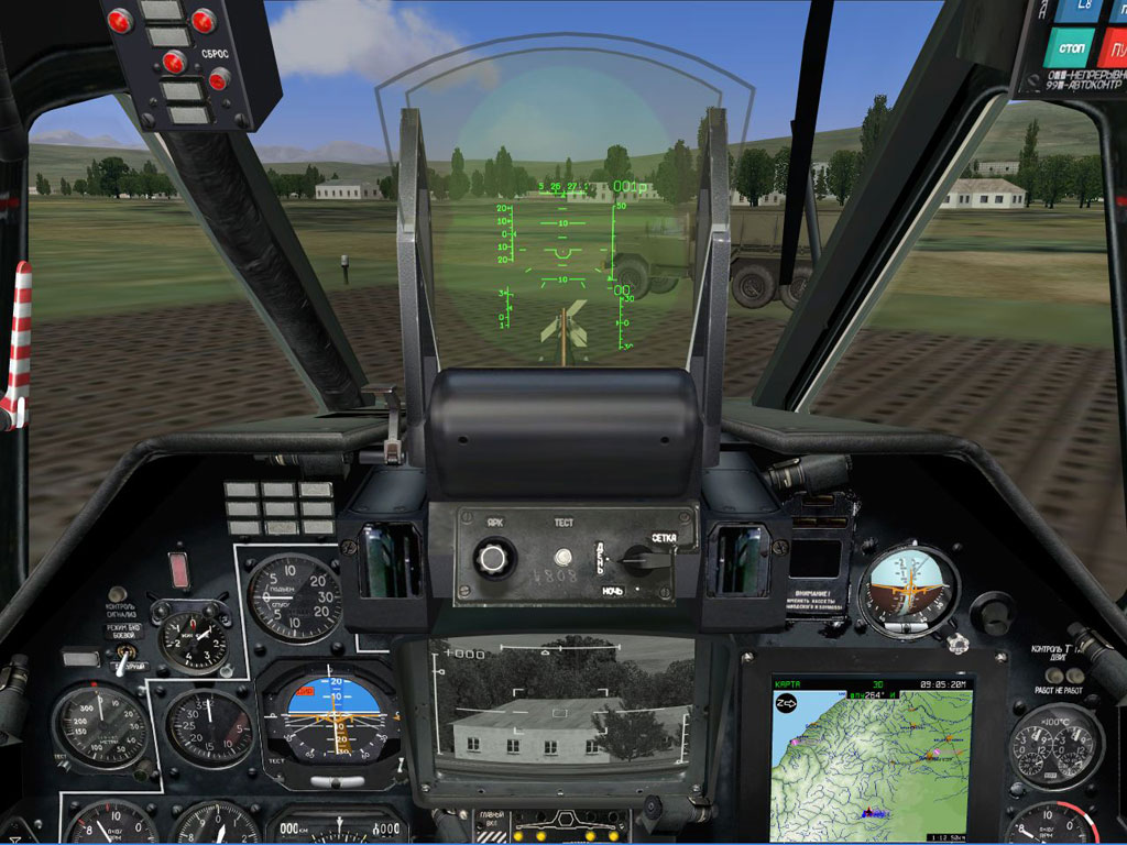
The head-up display (HUD) is modeled as a collimator optical device with focus set to infinity. This allows the pilot to look outside the cockpit through the HUD while still being able to read the symbols displayed on it.
Flight, navigation and targeting information is displayed on the HUD which is received from the «Ranet» information display system.
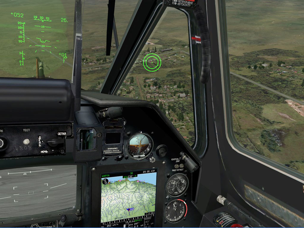
The HMS system is designed to hand-off targeting information to the «Shkval» system. The angular coordinates from the HMS, as determined by the pilot's line of sight, are transmitting to the «Shkval» targeting system for cueing.
The field of view limits are ±60° in azimuth and from -20° to +45° in elevation.
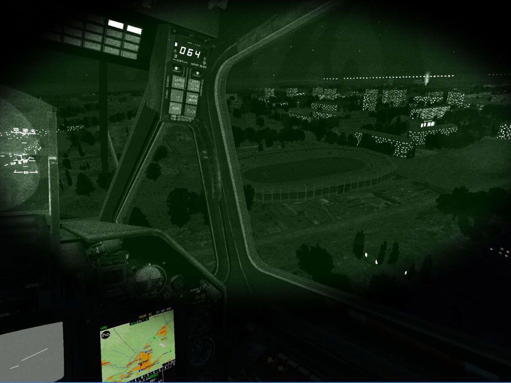
Night vision goggles (NVG) are included to allow the pilot to navigate in dark / low-light conditions.
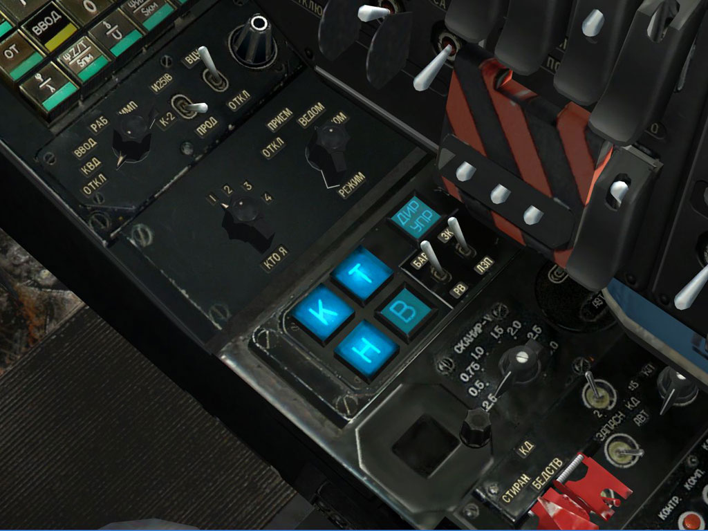
The autopilot system is integrated with the targeting and navigation systems and it produces control input for automatic flight system for deviation of the helicopter from the assigned attitude and altitude.
The Ts-061 inertial navigation system includes a gyro-platform and three accelerometers, designed for the determination of the flight direction and the attitude of the helicopter. The system also measures accelerations to calculate inertial speed and position of the helicopter.
The air data system is designed to receive input from various instruments, process these inputs and then present them to the pilot.
The doppler navigation system is used to determine the speed and angle of drift of the helicopter.
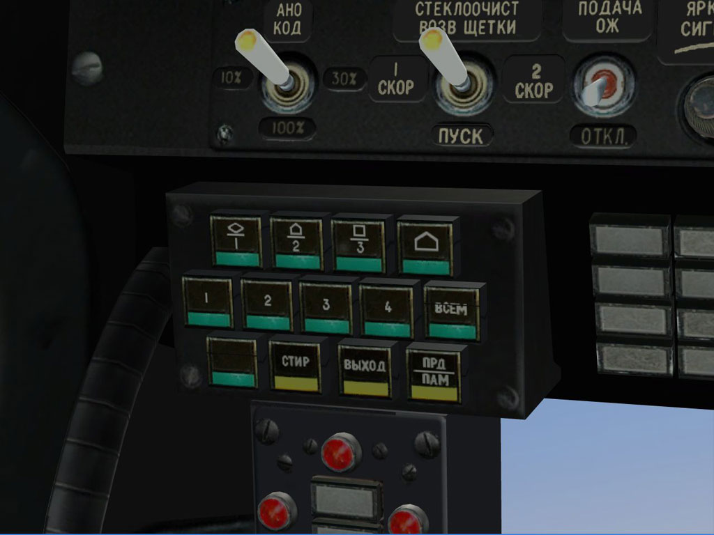
The data-link system allows exchange of up to 16 targets and reference points between helicopters. The automatic exchange of ownship coordinates is updated between the four aircraft of a flight. This data-link information is displayed on the ABRIS.
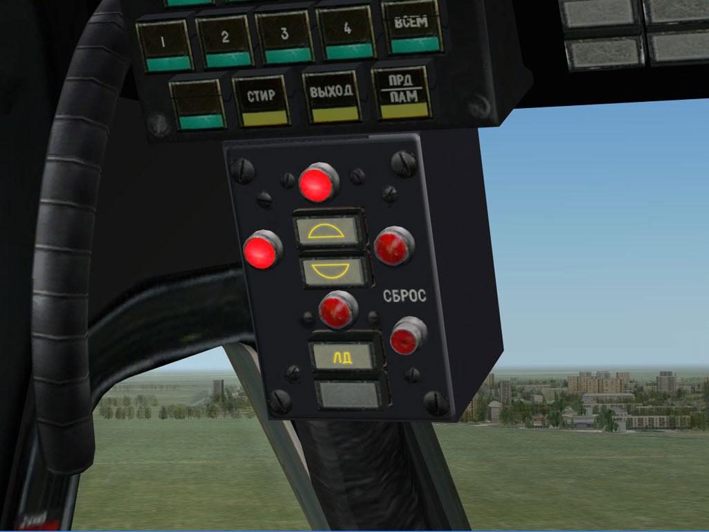
The laser warning receiver detects combat range-finders and laser designators. If the helicopter is lased, an indication of the type of laser is provided and the location quadrant that the laser is being detected from.
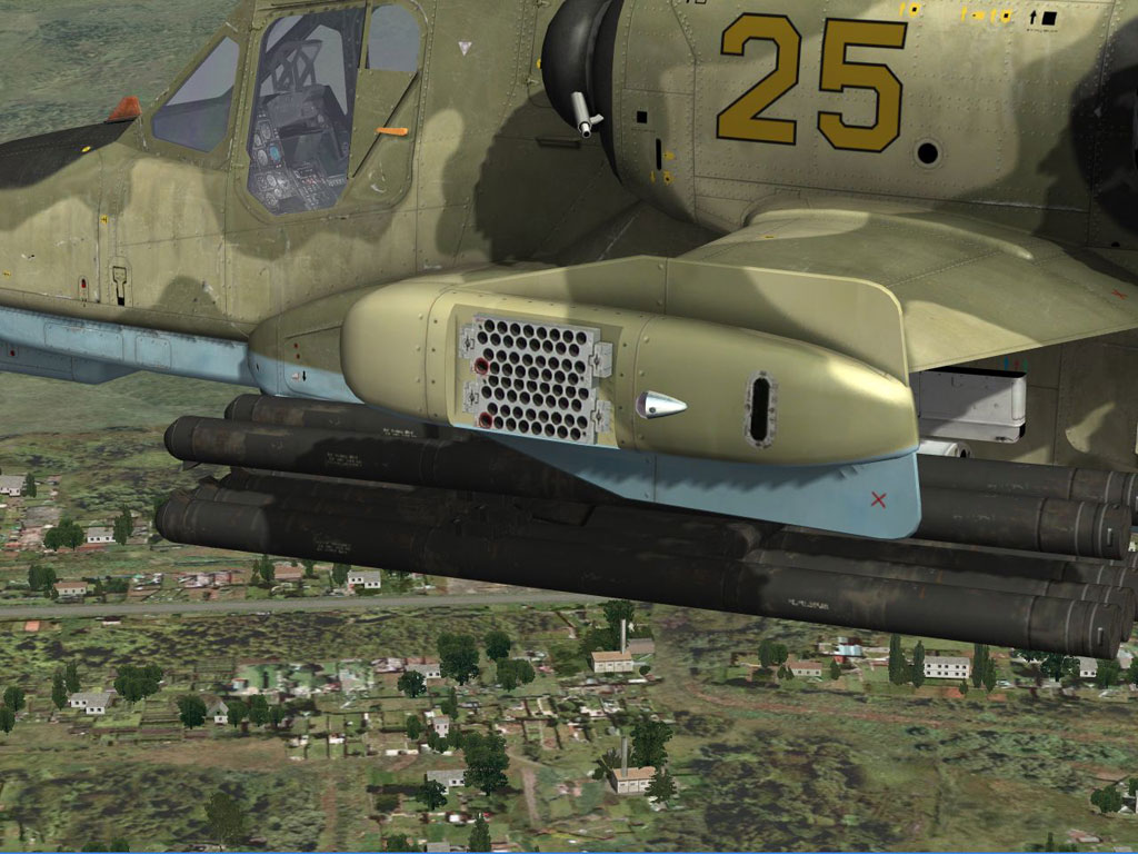
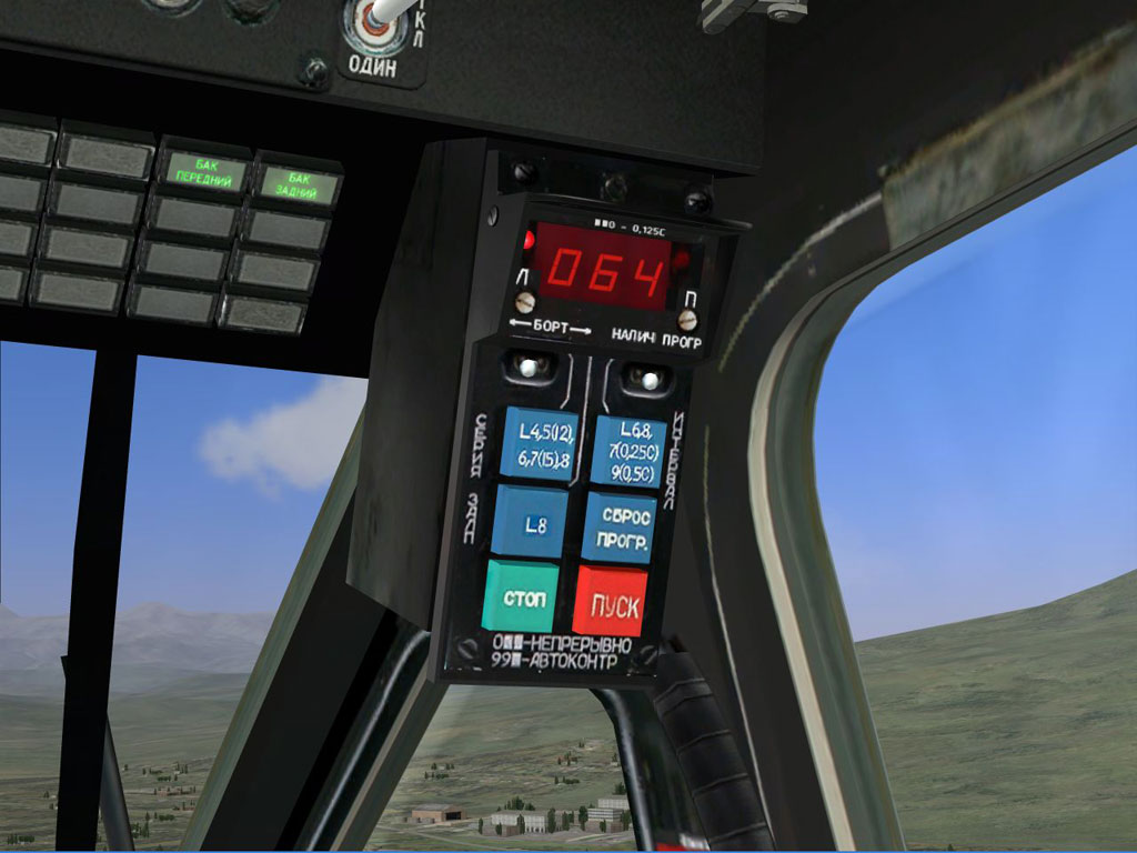
The countermeasures dispensers are located on the wing tips.
For the programming of countermeasure dispensers, the UV-26 control panel is used. Depending on the type of threat, the pilot can set the appropriate dispenser program for expending chaff and/or flares. The pilot can determine the number of flares to dispense in the volley, the time between each flare, and the time between volleys. Using the control panel it is possible to select with dispenser to use (left or right) and when to start or stop the dispensing program.
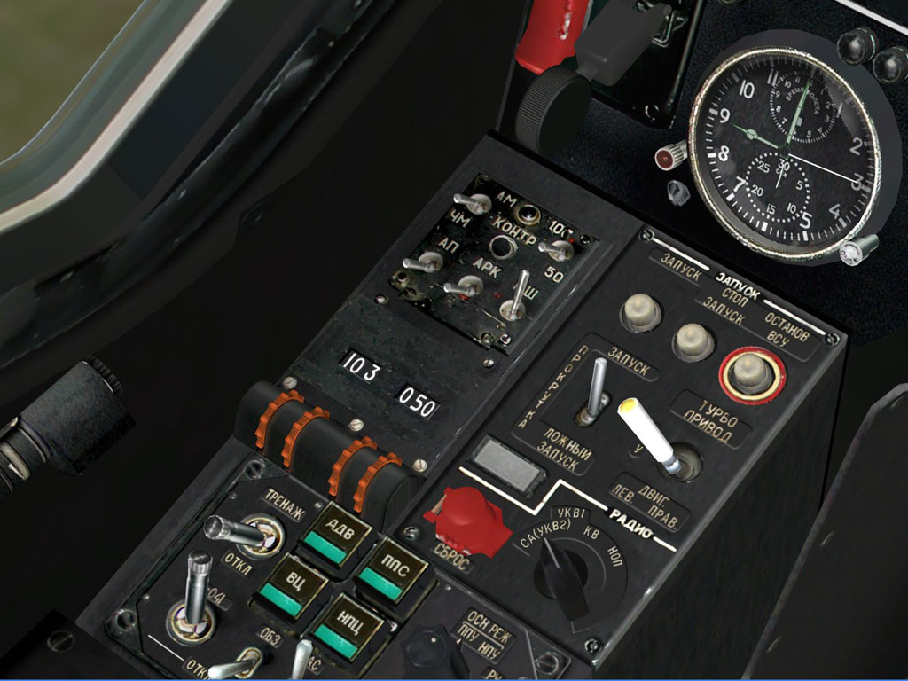
The R-800 UHF radio allows the pilot to communicate with the control tower and other aircraft. The R-800 is also used to send and receive encrypted data link information.
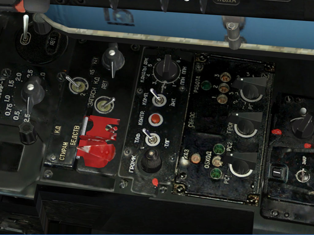
The ADF provides navigation using NDB (non directional beacon) or broadcasting radio stations. It can also monitor ground radio stations in the MW band.
The primary innovation regarding AI aircraft in «Black Shark» is the inclusion of a new and improved Flight Model (FM) system. In previous Eagle Dynamics products such as Lock On, the AI-aircraft FM did not reach a high-level of realism. For example: animations were sometimes used to supplement flight dynamics equations; this would in turn lead to unrealistic flight behavior in certain situations like high angles of attack and departures. This absence of detailed angle of attack modeling and the influence of cross wind led to problems when AI aircraft attempting to land in a cross-wind.
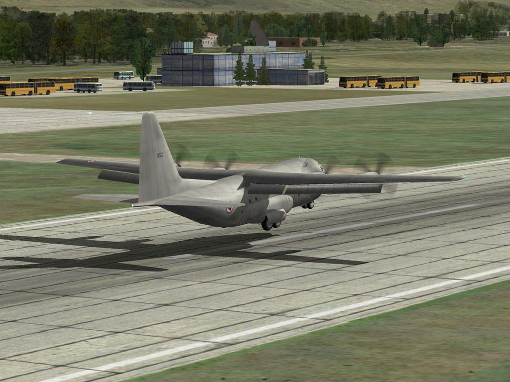
For «Black Shark», the same Standard Flight Model (SFM) will be used for AI-controlled aircraft that was used for player-controlled aircraft in «Lock On». This improved FM will provide much more realistic AI flight performance. Only the Advanced Flight Model (AFM) featured in the Su-25T of «Lock On: Flaming Cliffs» game (www.lockon.co.uk) is superior.
When using the SFM, the equations to derive aircraft motion take into account the unique inertial and aerodynamic characteristics of the aircraft. The engine model uses the factors of thrust and fuel-burn rate to further determine aircraft speed and altitude. These calculations allow the SFM to model realistic flight characteristics of aircraft (acceleration, rate of climb, maximum altitude, maximum and minimum speed, turn radius, instantaneous and sustained turn rates, range and flight duration). When converting the «Black Shark» AI aircraft to the SFM standard, it was necessary to modify more than 50 aircraft!
With this advancement in AI aircraft flight dynamics, it is now possible for the AI to conduct more advanced flight maneuvers and combat tactics:
These improvements also lead to more realistic combat between the player and AI aircraft.
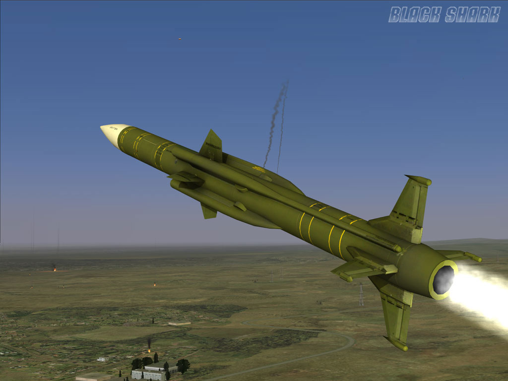
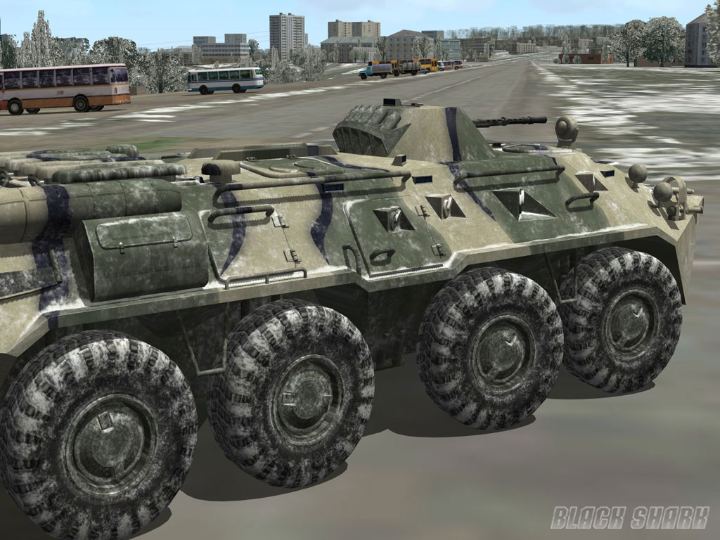
Ground vehicles, ships and weapons such as bombs, rockets, missiles and cannons have been significantly improved in «Black Shark». Improvements include:
The flight dynamic model of AI helicopters (hereinafter referred to as the «AI model») in «DCS : Black Shark» is a simplified version of the «advanced model», used for human-controlled helicopters. However, it is still based on the same equations of calculating realistic motion. The standard model provides realistic trajectories of motion and effects of control inputs during maneuvers.
The primary feature of AI model is an approximation of forces that are applied to the rigid body of a helicopter. With the AI model, aerodynamics forces on the chassis and forces from the rotors are calculated by using the same algorithms as in the advanced model with some simplifications to reduce unnecessary calculations. For example: the standard model rotor model calculates the inductive speed and the thrust in same manner as the advanced model but with a reduced number of calculated segments taken into account. The flap motion of blades and lift vector of the rotor are calculated using current flight parameters and control inputs.
The aerodynamic portion of the AI model includes a dynamic calculation of the fuselage as a source of aerodynamic drag and as an empennage that provides the flight stability. Every AI helicopter in the DCS series has its own unique set of empennages and fuselage air flow properties.
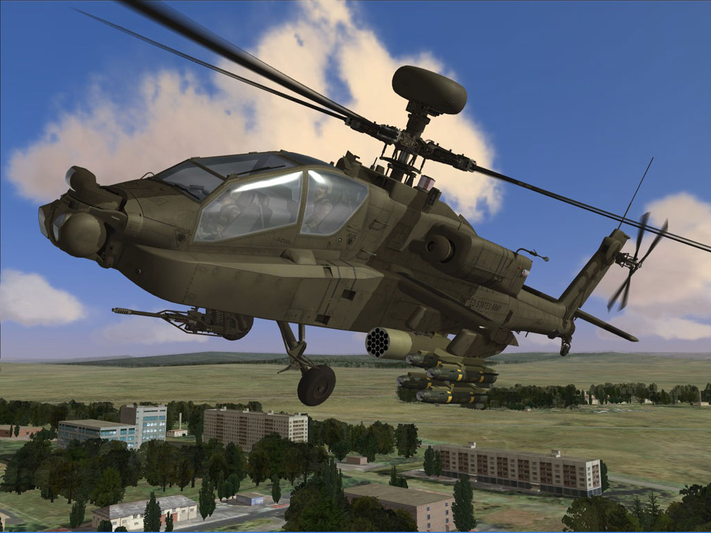
The AI model includes a power plant that is composed of engine(s) and a system that automatically maintains constant engine RPM. A fuel governor controls the engine power in relation to collective input and the difference between most efficient and current-setting rotor rpm. Maximum available power at any given air pressure, altitude and temperature is calculated by stored tables derived from the advanced engine model or from available manufacturers' data. The engine dynamic properties are modeled with engine power lag. The gas generator rotor RPM is set according to actual engine power.
As in the advanced model, the AI helicopters can use tricycle landing gear that is composed of wheels, a compression strut and a nonsymmetrical shock absorber.
The modeling of a unique fuselage and empennages that comprise an AI helicopter provide realistic flight properties when a helicopter is damaged. This is done by removing destroyed aircraft elements from the aerodynamic calculations. Tail rotor, stub-wings, parts of the main rotor (rotors), etc can be lost.
Even though controlled by the computer, the AI must still control the helicopter by inputs to the rudder pedals, cyclic and collective. The AI control algorithms take into account the flight limitations for each type of helicopter.
«DCS: Black Shark» operations will be based in the western Caucus region and will include portions of Russia, Georgia and a small part of Turkey. With Russia, special attention is paid to the Krasnodarskiy, Karachayrvo-Cherkesiya, Kabardino-Balkariya and Stavropol's key regions. Some of this area will be recognizable from «Flaming Cliffs», but «DCS: Black Shark» has added a considerable new amount of terrain, particularly much of Georgia. The «DCS: Black Shark» map is approximately 330,000 sq. km of ground and sea area.
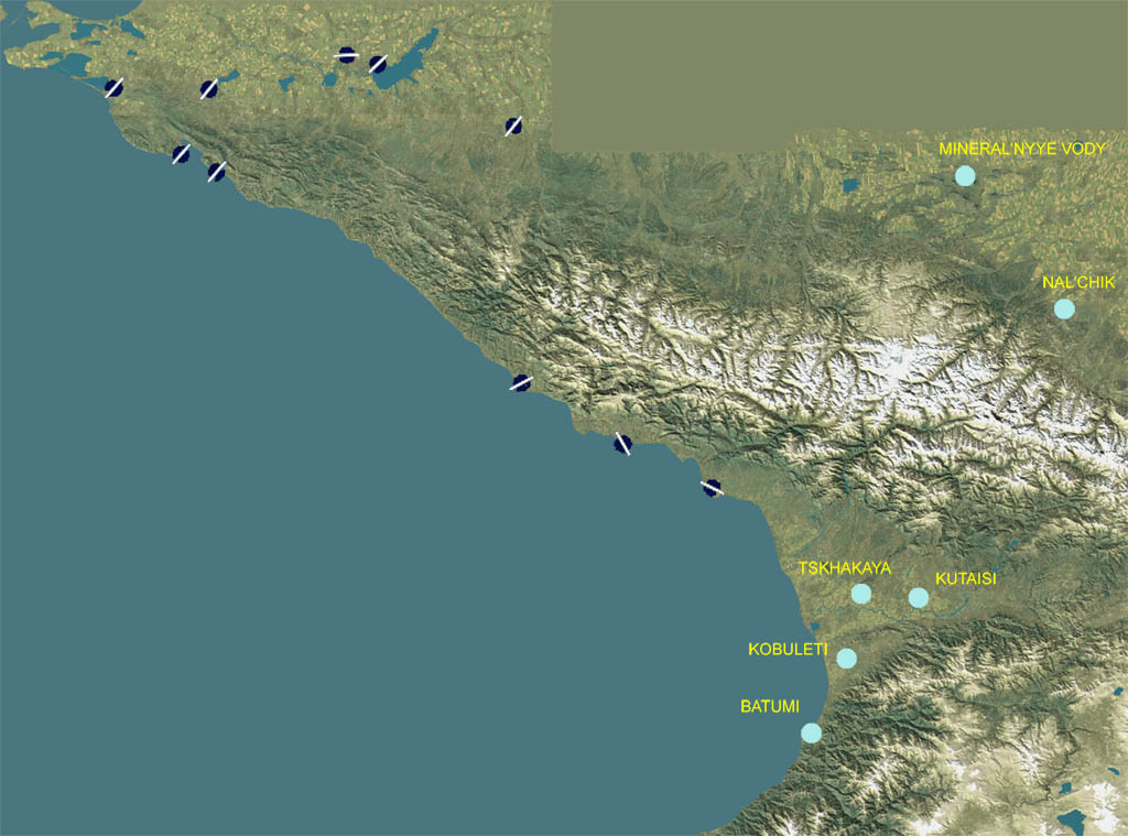
The map includes a wide array of topography that includes plains, agriculture fields, forests, hills, mountains, streams, rivers, lakes and seas.
The detail of the terrain height map has been increased in «DCS: Black Shark» in order to provide a more realistic height field to fly over in a helicopter at low altitude. Given the nature of attack helicopter operations, having a detailed height map was a must-have. Large portions of the «DCS: Black Shark» terrain height elevation matrix contain twice the number of triangles that were used to create the «Flaming Cliffs» terrain.
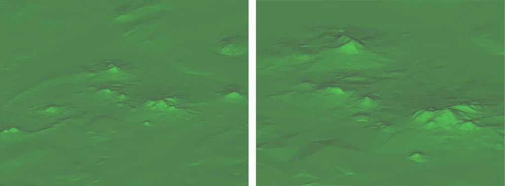
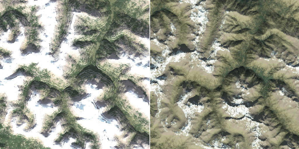
The terrain elevation matrix is particularly detailed in the Mineralnye Vody area of the map. The left image above shows the elevation matrix from the same height as the previous images. The right image above shows the center of the area but at twice the scale (zoomed in). Note that the mesh is still looking very detailed.
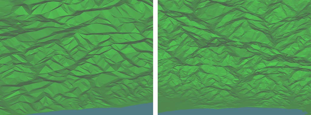
Two examples of increased terrain mesh detail. To the left is the area between Tuapse and Sochi and to the right is an example of the Batumi region.
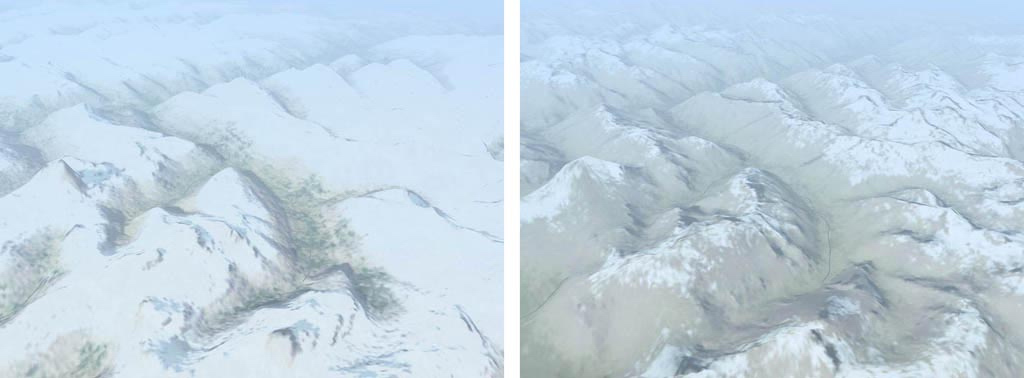
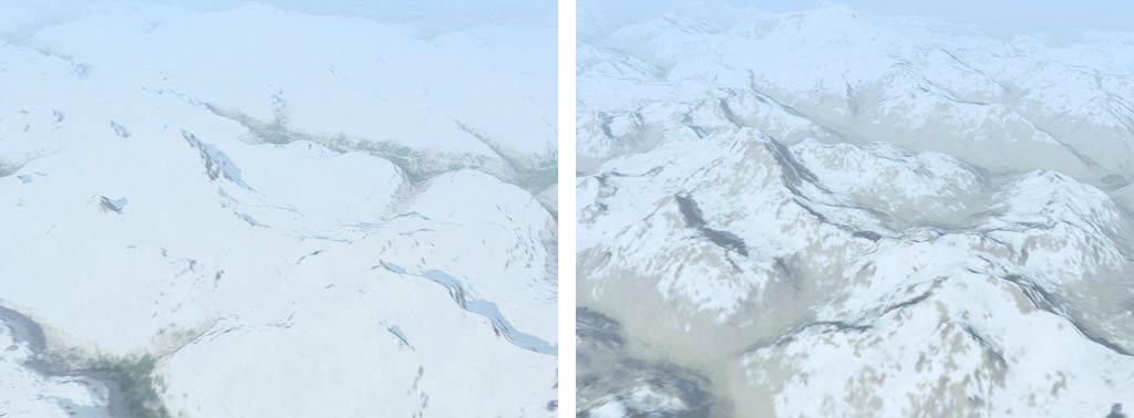
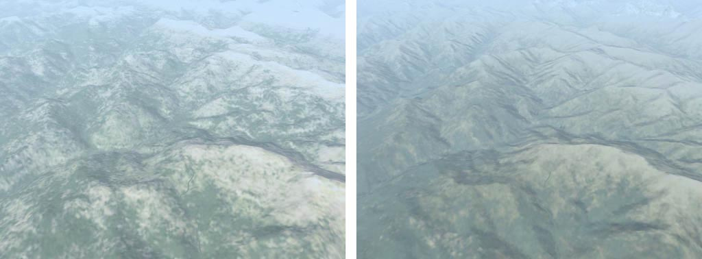
In addition to a finer terrain height mesh, we have also increased the resolution of the terrain textures for population centers, agricultural fields, and airbases. The other texture areas have been modified to more accurately conform to the terrain height matrix. The below images compare the same region in «Flaming Cliffs» and «DCS: Black Shark». The combination of the more detailed height map and the high-resolution ground textures provide for a much more detailed terrain environment to fly and fight over.
Examples of normal terrain mesh and textures on left and improved terrain mesh and improved textures on the right.
With the expanded terrain, we have also added numerous towns, cities, roads, rail lines, power lines, forests, rivers, streams and many other features to populate the world. In regards to both the new and existing terrain from «Flaming Cliffs», we have increased the detail and object / road density. Many of the buildings will also receive a face-lift with upgraded detail.
To support air operations in the new areas, «DCS: Black Shark» has added six new airfields, two in Russian and four in Georgia. These new air bases are represented by the light-blue dots in the image at the beginning of this section.
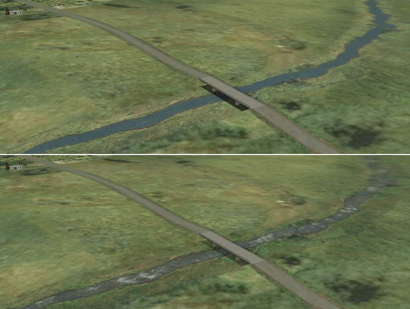
To give the small streams a more natural look, «DCS: Black Shark» will include animation to the water texture. The below images compare streams in «Flaming Cliffs» and «DCS: Black Shark».
Static example of river on at the top and animated river below
DCS: Black Shark features an authentic model of radio navigation equipment. The DCS world includes various radio navigation aids available in the theater of operations modeled in the simulation, including:
Although not used by the Ka-50, the simulation code supports various other types of radio navaids for future flyable aircraft, theatres of operation and campaign scenarios, including:
The DCS Ka-50 model includes the following radio equipment:
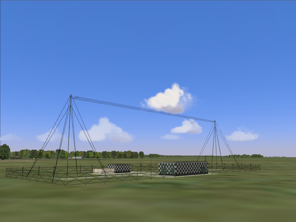
In general, airfields are equipped with outer and inner NDB locator beacons for each end of every runway at 4000 m. and 1300 m. respectively. Some airfields are configured differently according to local conditions, such as sea or mountain proximity. Each beacon in the simulation is assigned its realistic frequency in the 150-1750 kHz range and Morse code ID. Additionally, each NDB locator beacon includes a co-located marker beacon operating at 75 mHz. The map also includes realistically placed independent NDBs with individual frequencies and IDs.
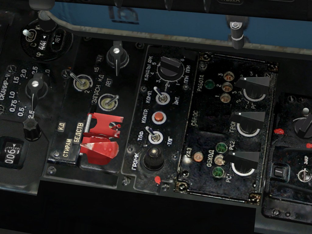
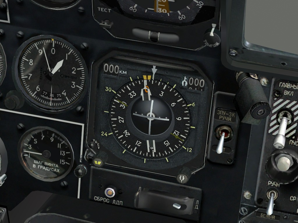
To conduct radio navigation, the Ka-50 pilot can use the ARK-22 ADF and the ABRIS AMMS.
The ARK-22 ADF controls the Radio Magnetic Indicator (RMI) needle on the Horizontal Situation Indicator (HSI), pointing it in the direction of the transmitting signal. Using the ADF, the pilot can select one of eight preset channels, each of which stores two radio frequencies. Upon reaching the transmitter of the currently selected frequency, the ADF automatically begins homing on the second and vice versa. Alternatively, the pilot can manually select which of the two frequencies on the selected channel to home on. For example, the first frequency in a given ADF channel may be set to home on the airfield outer locator beacon and the second on the inner locator beacon, etc. The pilot can verify selection of the correct beacon by configuring the ADF to provide an audio transmission of the beacon's ID. While in real life the frequencies for each ADF channel are set by ground personnel, the DCS player can edit these in the ADF configuration files outside the simulation.
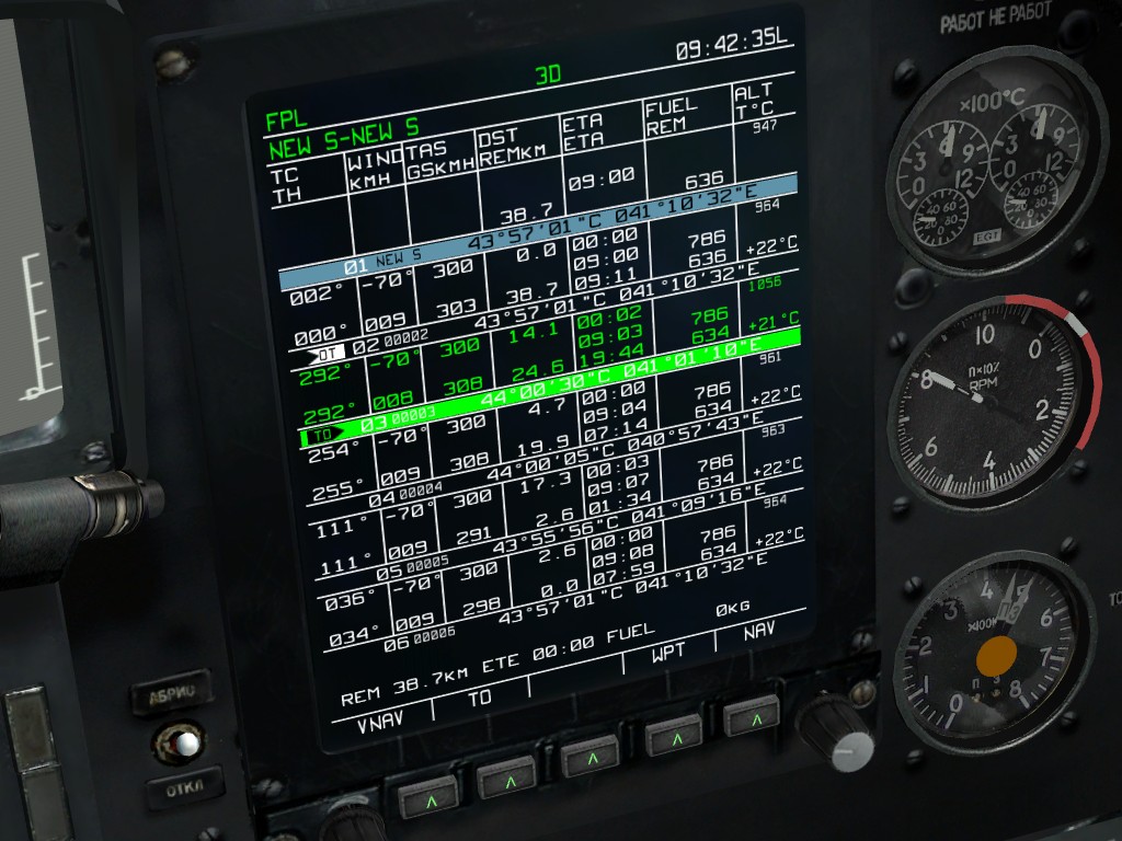
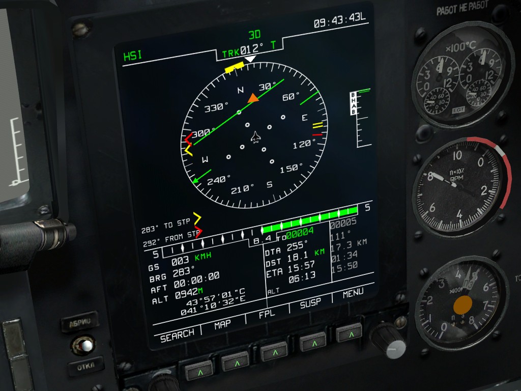
The ARK-22 ADF can also be slaved to the R-800L1 UHF radio. In this case, the RMI needle on the HSI is directed toward the transmitter on the frequency currently selected for the R-800L1 radio. For example, the flight leader can maintain bearing to his wingman when the wingman is transmitting a radio call. The R-800L1 radio can also be used to tune the ADF to any broadcasting station, such as the commercial «Radio Mayak» in Maykop city. The DCS player can load audio files into specially assigned folders to be played when he tunes the radio to the frequency and modulation setting of the broadcasting station.
Using the ABRIS AMMS, the pilot can select any radio station in the database to guide to or obtain more information on, including its code and ID. Using the ABRIS Options page, the player can assign the ABRIS RMI 1 and/or 2 needles on the ARC and HSI pages to display the radio beacon azimuth.
The SPU-9 intercom system provides audio and microphone transmission for the pilot. It can be set to UHF1 (R-828), UHF2 (R-800L1), KV (ADF and Marker Beacon), and NOP (ground link).
The R-828 radio is used for communication with combat ground units and is not part of the navigation equipment.
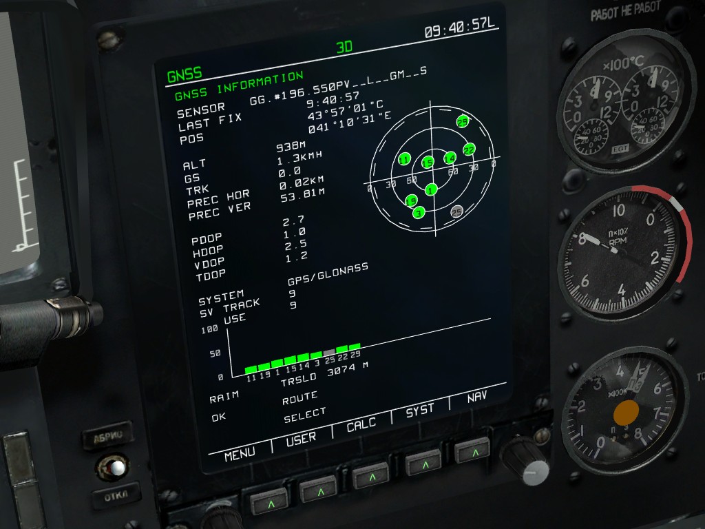
DCS: Black Shark features an expanded ground personnel and airfield tower radio communications menu. Having provided power to and properly configured the radios, the player can communicate with the ground crew to request payload changes, fuel loads, sighting devices (HMS or NVG), electric power to the aircraft, etc. The player can communicate with the tower to request permission for engine start, taxi, test hover, etc.
The DCS radio physics model calculates every transmission in real time and determines the local signal strength according to numerous variables, including time of day (ionosphere effect), surface type (rough terrain, paved surface, water, etc.), distance to transmitter, transmitter power, etc. Because radio traffic is carried «live,» reception can be interrupted at any point by either natural or artificial interference, such as terrain topology or radio configuration. For example, if the player changes his radio frequency, reception will cease, but can resume at its actual point upon reconfiguring the radio back to the transmitter's frequency. AI units react to radio calls only if transmission is successful.
The frequency configuration files allow the DCS player to configure the various frequencies used by in-game units, including own flight, tower, AWACS, etc.
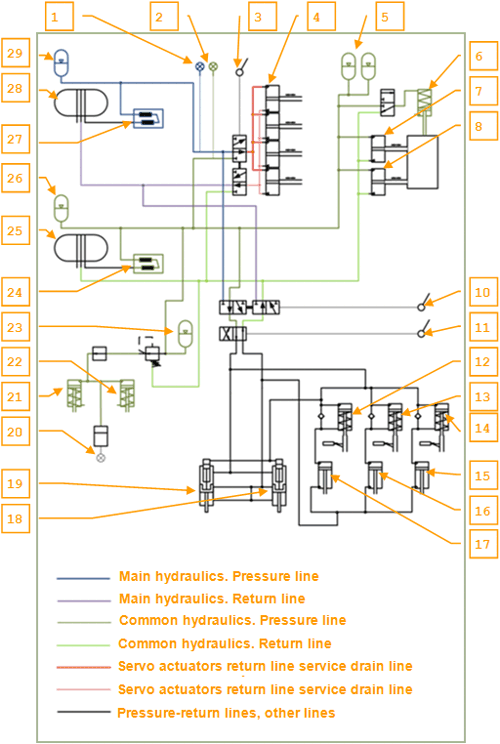
The Ka-50 hydraulic system is used to provide hydraulic power to various helicopter systems. This consists of two subsystems:
Each system consists of a hydraulic pump, a hydraulic fluid tank, filters, valves, pipes and control elements. The pressure source for both systems is provided by variable displacement pumps. The main system's pump is mounted on the left accessory gearbox of the main gearbox, and it operates when the rotors are driven by the engines and also when in autorotation. The common system's pump is mounted on the aft accessory gearbox of the main gearbox, and it operates when the rotors are turning or when the APU is on.
There are hydraulic accumulators in each system to prevent pressure oscillations. In the brake system there is a separate accumulator to power the parking brakes (for up to 2 hours) after engines shut down, or power the brakes during taxi in case of a common system failure. The main system's tank has a capacity of 13 liters and the common system tank has a capacity of 17 liters.
Hydraulic system control is through fluid pressure and temperature indicators and the pressure switches. The indicators are located on the upper part of the cockpit control panel. The indicators include marks that specify the operating range of each indicator:
Pressure switches are installed in:


